Non-contact three-dimensional optical measuring head and method for in-situ measurement of numerical control machine

A three-dimensional optical, numerically controlled machine tool technology, used in measuring/indicating equipment, metal processing mechanical parts, metal processing equipment, etc., can solve the problems of measurement force system error, measurement efficiency influence, damage to the surface of the workpiece, etc., to achieve high precision, improve The effect of equipment utilization and low cost

Inactive Publication Date: 2010-12-15
HEFEI UNIV OF TECH
View PDF4 Cites 36 Cited by
  • Summary
  • Abstract
  • Description
  • Claims
  • Application Information

AI Technical Summary

Problems solved by technology

[0004] At present, the in-situ measurement system of CNC machine tools mainly uses the trigger probe, which is similar to the working mode of the traditional three-coordinate measuring machine. Since the trigger probe is required to measure the three-dimensional dimensions of the workpiece, it is inevitable to introduce contact measurement. There are deficiencies in the method, such as the probe needs to touch the surface of the workpiece to be measured during the measurement process, and mechanical force interaction occurs. The measurement force will introduce systematic errors and random errors, and will damage the surface of the workpiece. Due to the need for multiple touches and lifting the probe will affect the measurement efficiency

Method used


Image

  • Non-contact three-dimensional optical measuring head and method for in-situ measurement of numerical control machine
  • Non-contact three-dimensional optical measuring head and method for in-situ measurement of numerical control machine
  • Non-contact three-dimensional optical measuring head and method for in-situ measurement of numerical control machine

Examples


Embodiment Construction

[0024] In this embodiment, the vertical CNC milling machine XD30A of Dalian Machine Tool Group and the FANUC 0i Mate CNC system are used.

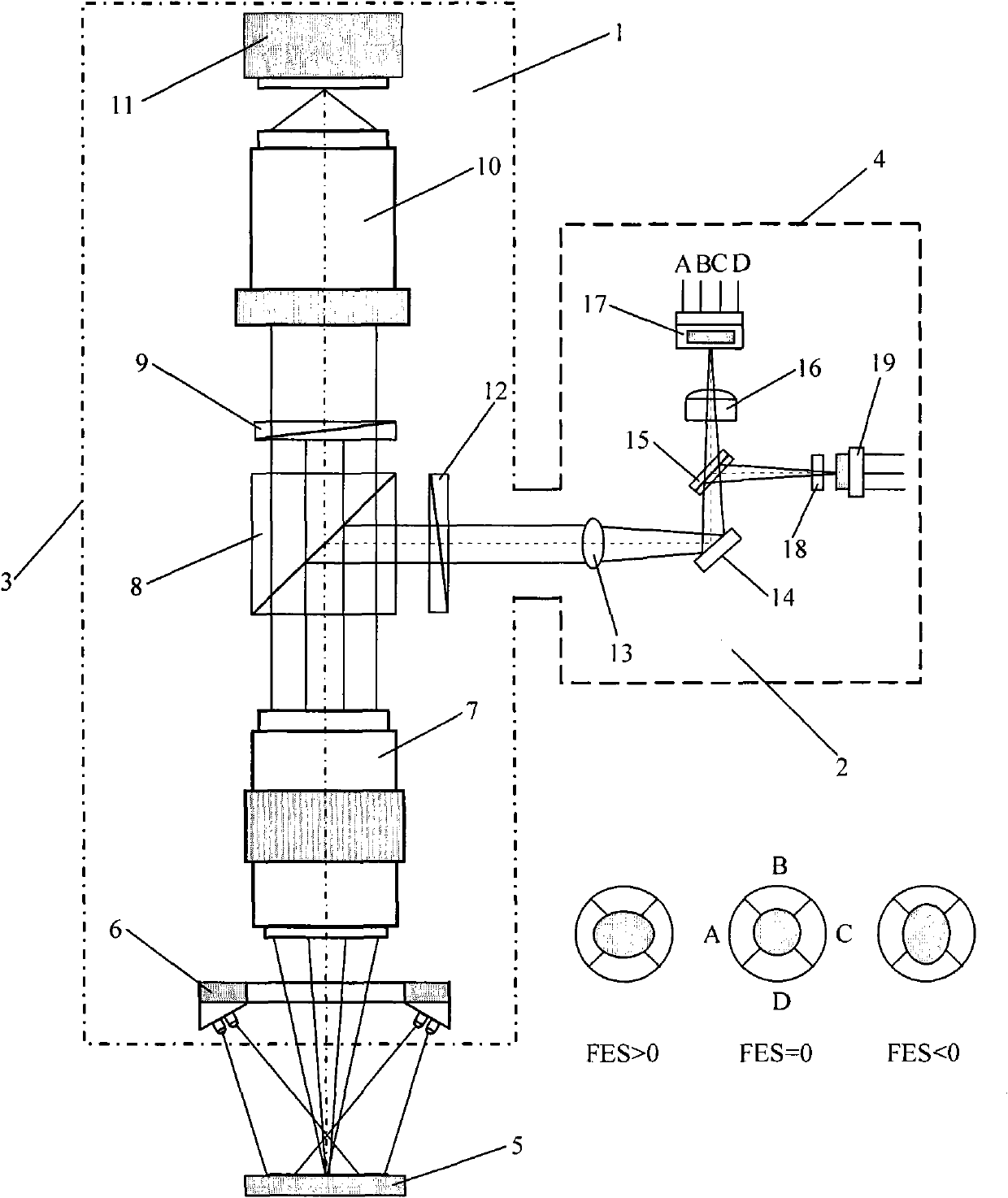
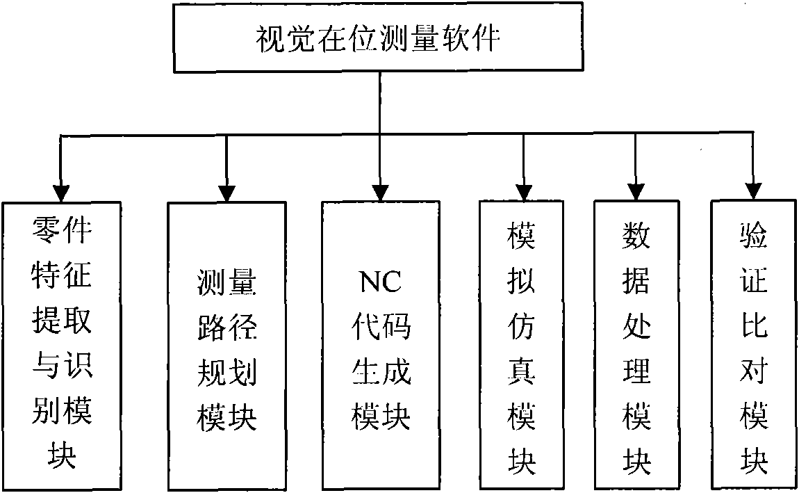
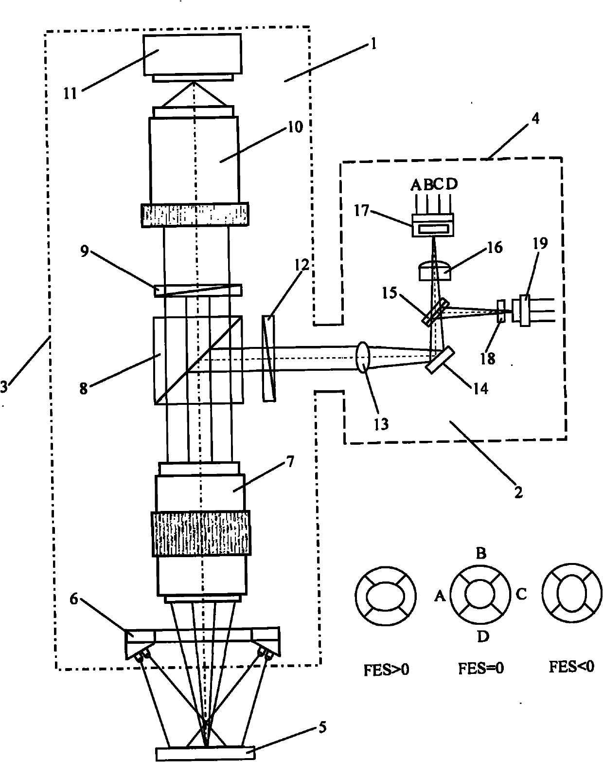
[0025] see figure 1 , The in-situ measurement system for CNC machine tools in this embodiment consists of a vertical CNC milling machine, a non-contact three-dimensional optical probe, an industrial computer and visual in-situ measurement software. The non-contact three-dimensional optical probe is installed on the Z-axis of the main body of the machine tool, and the Z-axis coordinate value of the non-contact three-dimensional optical probe is defined as the Z-axis coordinate value of the vertical CNC milling machine. The input end of the servo system is connected to the CNC system, and the output of the servo system is The end is connected with the motor of the vertical CNC milling machine, the CNC system drives the motor to rotate through the servo system, the CNC system is connected with the non-contact 3D optical probe, and the industr...


PUM


Abstract

The invention discloses a non-contact three-dimensional optical measuring head and a non-contact three-dimensional optical measuring method for in-situ measurement of a numerical control machine, which are characterized in that: the non-contact three-dimensional optical measuring head consists of an image measuring system and a focus positioning system. The non-contact three-dimensional optical measuring method comprises the following steps of: firstly, making a focus judgment on the image measuring system by using an astigmatism method, determining a measuring plane, positioning the non-contact three-dimensional optical measuring head in a Z-axis direction at the same time and acquiring a Z-axis direction positioning value of a surface characteristic point of a workpiece; secondly, performing two-dimensional image measurement on basic geometric elements, of the workpiece, on the measuring plane by using a surface measuring method in image projection measurement to obtain two-dimensional plane coordinate values of the surface characteristic point of the workpiece; and finally, combining the two-dimensional plane coordinate values with the Z-axis direction positioning value to obtain the three-dimensional coordinate values of the surface characteristic point of the workpiece. The non-contact three-dimensional optical measuring head and the non-contact three-dimensional optical measuring method can effectively perform high-precision in-situ measurement of the geometric size of the workpiece processed by the numerical control machine, shorten the manufacturing period of products effectively and guarantee product quality.

Description

technical field [0001] The invention relates to a non-contact three-dimensional optical measuring head for a numerically controlled machine tool and a measuring method thereof. Background technique [0002] With the rapid development of advanced manufacturing technology, more and more new challenges have been put forward for precision measurement technology. Numerical control technology is the basic core of advanced manufacturing technology, and the quality control of numerical control machining process is one of the urgent problems to be solved in the field of precision measurement, which directly affects product quality and production efficiency. Although traditional manual measurement and off-line measurement are still widely used, they cannot meet the needs of the development of modern manufacturing. [0003] The in-situ measurement technology of CNC machine tools integrates processing and measurement to realize automatic measurement during processing. Measurement is n...

Claims


Application Information

Patent Timeline
Patent Type & Authority Applications(China)
IPC IPC(8): B23Q17/24
Inventor 卢荣胜夏瑞雪董敬涛李楠楠
Owner HEFEI UNIV OF TECH
Why Eureka
Try Eureka