In situ leaching injection process

A technology of in-situ leaching and liquid injection, which is applied to the improvement of process efficiency, mining fluids, drilling equipment and methods, etc., can solve problems such as poor stability, achieve strong adaptability, improve rare earth leaching rate, and reduce waste leaching. mineral effect

Active Publication Date: 2010-12-15
JIANGXI RARE EARTH & RARE METALS TUNGSTEN GRP HLDG CO LTD
View PDF5 Cites 18 Cited by
  • Summary
  • Abstract
  • Description
  • Claims
  • Application Information

AI Technical Summary

Problems solved by technology

[0005] The purpose of the present invention is to provide an ion-adsorption type rare earth in-situ leaching liquid injection process, which has a high rare earth leaching rate, reduces the residue of mother liquor in the ore body, reduces environmental pollution, has high concentration of mother liquor, and has a single ore leaching agent. Low power consumption, simple operation, wide application range, and remarkable environmental protection effect solve the problems of blind spots in ore leaching and poor stability of slopes during liquid injection, and realize the controllability of the flow direction, flow rate, and injection strength of ore leaching agents and the controllability of liquid injection. The connection between the system and the liquid collection system also solves the in-situ leaching technical problems of deeply buried ore bodies, poor permeability ore bodies and "chicken nest" ore bodies

Method used


Image

  • In situ leaching injection process
  • In situ leaching injection process
  • In situ leaching injection process

Examples


Embodiment Construction

[0038] Referring to the accompanying drawings, the specific implementation method of the technical solution of the present invention is as follows:

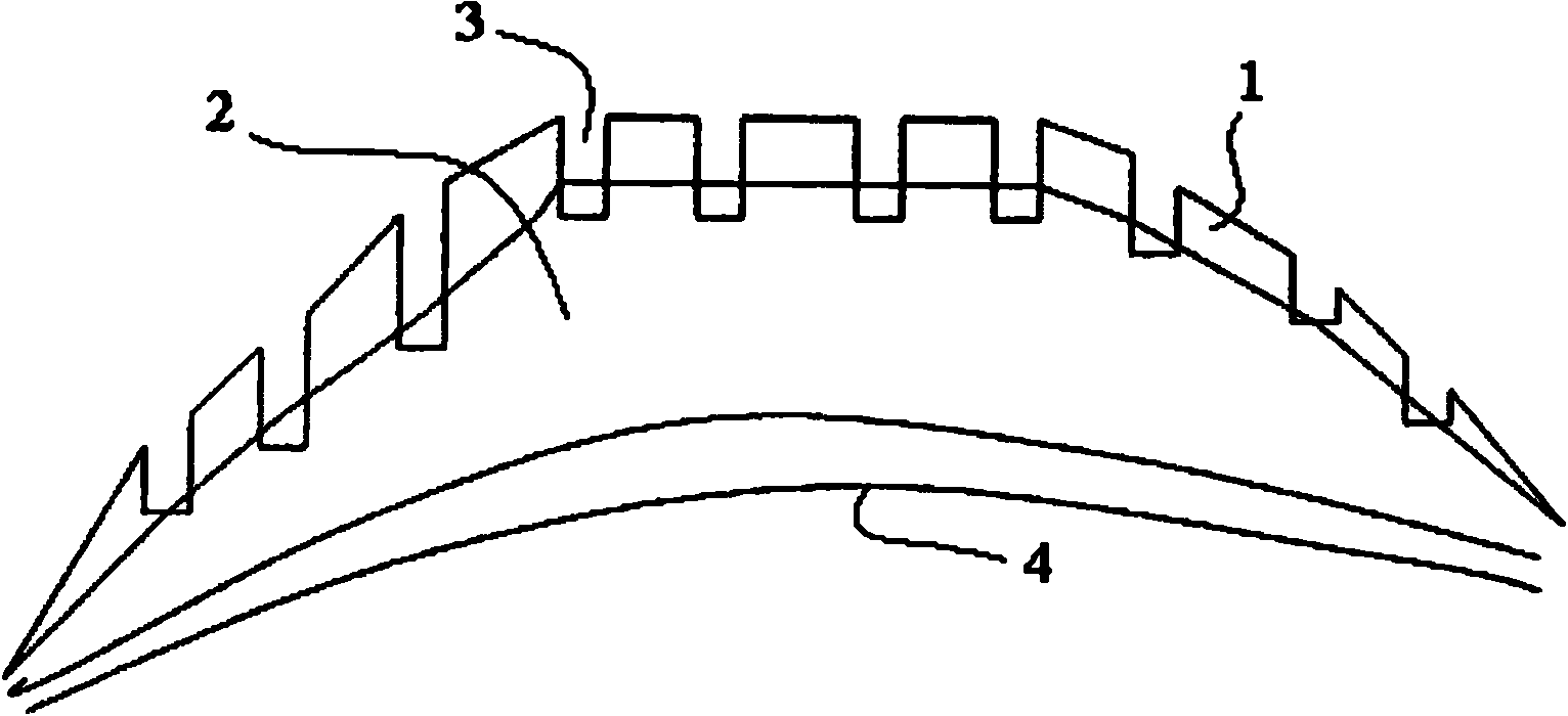
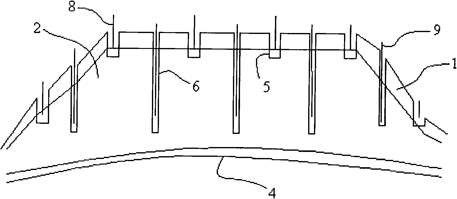
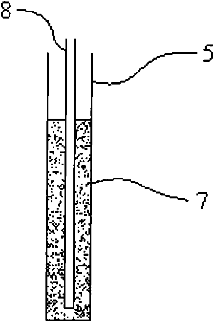
[0039] Such as figure 2 As shown, according to the spatial distribution of the ore body, the change of the thickness of the ore body, the permeability of the ore soil, and the engineering layout of the liquid collection system, etc., the special Luoyang shovel is used to set the static pressure liquid injection shallow well 5 and the general Luoyang shovel is used to set the closed well 5. Pressure deep well 6, forming a liquid injection network distributed at intervals; the distance between liquid injection wells is generally 2.5×2.5 meters, but if the ore soil is medium-coarse sand structure, it can be adjusted to 3×3 meters, and it can be adjusted to 3 meters if it is mainly clay and silt. 2 x 2 meters. The well depth of the shallow well 5 directly reaches 1 to 2 meters below the ore layer 2, and the well depth of the deep w...


PUM

PropertyMeasurementUnit
diameteraaaaaaaaaa
pore sizeaaaaaaaaaa

Abstract

The invention discloses an ion adsorption rare-earth in situ leaching injection process, which is characterized by comprising the following steps of: setting an injection network with shallow injection wells and deep injection wells distributed at intervals according to mineral body space layout condition, mineral body thickness change condition, mineral soil permeability, project layout of a liquid receiving system and the like; and injecting the shallow injection wells and then injecting the deep injection wells in an injection process, and finally injecting top water to the shallow injection wells and the deep injection wells together. The in situ leaching injection process has the advantages of rare-earth leaching rate, high mother solution concentration, little mineral mother solution residue, low single leaching agent consumption, simple operation, wide application range and remarkable environment-friendly effect, meanwhile solves the problem of poor stability of a leaching dead zone and an injection process slope, and realizes controllability of flow direction, flow rate and injection strength of the leaching agent.

Description

technical field [0001] The invention relates to an in-situ leaching liquid injection process, in particular to an ion-adsorption type rare earth in-situ leaching liquid injection process, belonging to the technical field of in-situ leaching and mining. [0002] The term "top water" in this specification refers to the "industrial top water" controlled by a certain ratio of "solid-liquid ratio" after the "leach solution" is injected into the ore-bearing body and the "leach" process is completed. The "injection well" is injected into the mountain. Under the action of "top water", the rare earths that have been "exchanged" are combined with the part of the leaching solution that has completed the "ion exchange" or has not completed the exchange process injected earlier to form a rare earth-containing mother solution. Simply put, after the leaching process is completed with the leaching agent, the liquid injection process using "supernatant" or clear water is aimed at "squeezing" ...

Claims


Application Information

Patent Timeline
Patent Type & Authority Applications(China)
IPC IPC(8): E21B43/00E21B43/20
CPCC22B3/04E21B7/00C22B3/02C22B59/00E21B43/28Y02P10/20E21B43/00E21B43/20E21B43/29
Inventor 谭尧峰刘彦
Owner JIANGXI RARE EARTH & RARE METALS TUNGSTEN GRP HLDG CO LTD
Why Eureka
Try Eureka