Solar power generating equipment

A technology for power generation equipment and solar energy, which is applied in the fields of solar thermal power generation, mechanical power generation by solar energy, mechanical equipment, etc., can solve the problems of high investment, leakage of nuclear power generation, environmental pollution by thermal power generation, etc., and achieves simple equipment structure and wide application range. , the effect of low product cost

Inactive Publication Date: 2010-12-15
杨宝才
View PDF0 Cites 6 Cited by
  • Summary
  • Abstract
  • Description
  • Claims
  • Application Information

AI Technical Summary

Problems solved by technology

However, there are some defects in the existing power generation methods: thermal power generation will pollute the environment, hydropower generation is harmful to the natural ecology, nuclear power generation has the risk of leakage, and wind power generation has high costs due to scattered and interconnected units.
However, these two photovoltaic cells are restricted by the physical properties of the materials, and the photoelectric conversion efficiency is low. What's

Method used


Image

  • Solar power generating equipment
  • Solar power generating equipment

Examples


Embodiment Construction

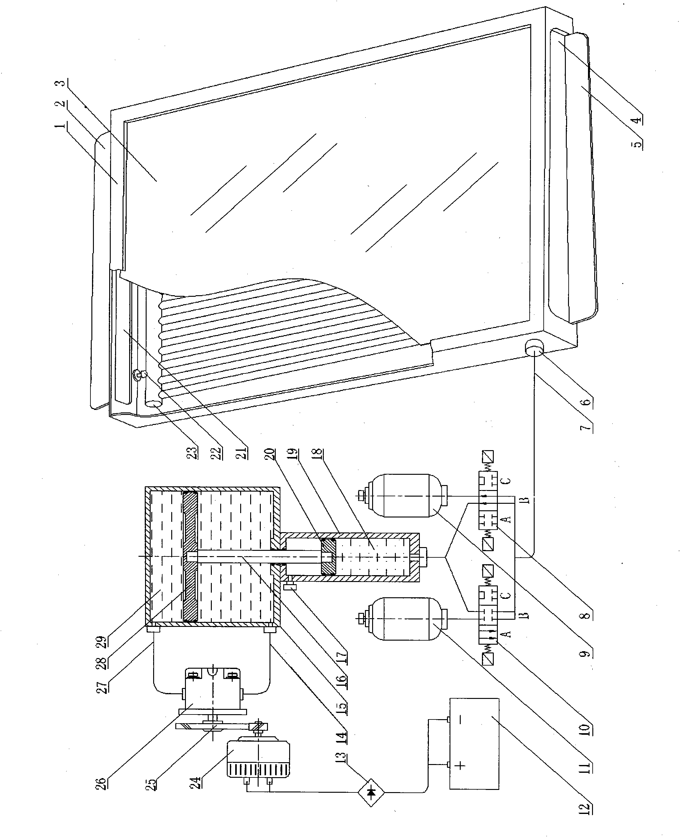
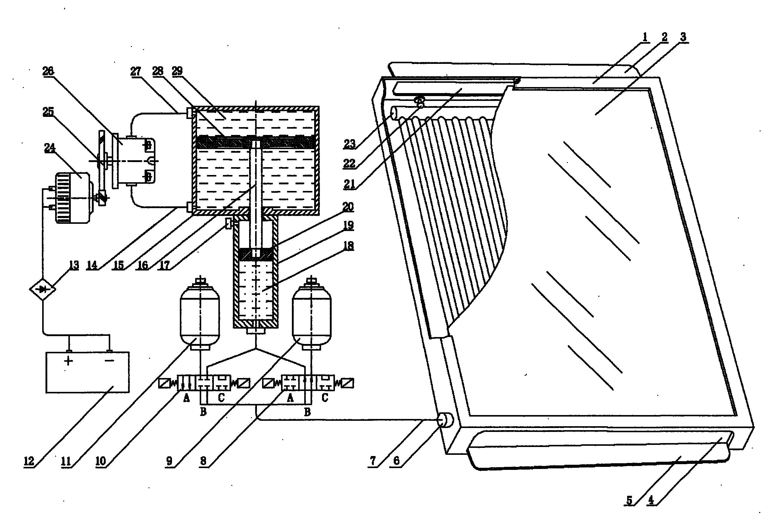
[0013] See figure 1 , A solar power generation equipment, which consists of a driving device, a power device, a generator and a battery.

[0014] The driving device includes a heat exchanger 1, a positive pressure accumulator 9, a negative pressure accumulator 11, and a drive cylinder 19. These hydraulic components are connected to a closed circuit drive system through a hydraulic pipe 7 and a reversing valve 8, and a reversing valve 10. The system is filled with working fluid 18.

[0015] The power plant includes a power cylinder 15 and an actuator 26, which are connected by a circulation pipe 14 and a circulation pipe 27 to form a closed-circuit power system, in which a liquid medium 29 is filled.

[0016] The piston 20 in the driving cylinder and the piston 28 in the power cylinder are connected as a whole by the piston rod 16. The output shaft of the actuator 26 in the power plant is rotationally connected with the generator shaft through the transmission part 25, and the output...


PUM


Abstract

The invention relates to solar power generating equipment which comprises a driving device, a power device, a generator and a storage battery, wherein the driving device comprises a heat exchanger, an energy accumulator and a driving cylinder which are connected through hydraulic tubes and change valves to form a closed-loop driving system, and the system is filled with operating fluid; the power device comprises a power cylinder and a hydraulic motor which are connected through a circulating tube to form a closed-loop power system, and the system is filled with the operating fluid; and a piston in the driving cylinder and a piston in the power cylinder are connected into a whole through a piston rod. In the daytime, the operating fluid in the driving system absorbs solar heat, expands continuously to produce pressure and drives the generator to operate and generate electricity through the driving cylinder, the power cylinder, the hydraulic motor and a transmission device. At night, the operating fluid in the driving system contracts continuously due to temperature reduction to produce negative pressure and drives the generator to rotate reversely and generate electricity through the driving cylinder, the power cylinder, the hydraulic motor and the transmission device. In the invention, conventional mechanical devices can be used for converting solar energy into electric energy by using the natural characteristics of diurnal temperature change and fluid expansion with heat and contraction with cold. The solar power generating equipment not only can be used independently, but also can be used for forming a large-scale generating system. While in use, only simple regular maintenance is needed without any cost. The invention provides a new approach for effectively utilizing solar energy and can produce great economical benefits and social benefits in modern society where low-carbon lifestyle is proposed and energy resource crisis becomes more and more serious.

Description

1. Technical Field [0001] The invention relates to power generation equipment, in particular to a solar power generation equipment. 2. Background technology [0002] Energy is the material basis for human existence. With economic development and social progress, human demand for energy is increasing. For a long time, people's unrestrained exploitation and use of mineral energy has not only caused a sharp decrease in its reserves, but also brought global environmental pollution and ecological damage, posing a threat to human survival and development, which forced people to develop as soon as possible And the use of new alternative energy sources. [0003] The sun is emitting energy to the earth at all times. As long as it can be received and utilized, there is no need to worry about its source; the use of solar energy does not require transportation, costs, and does not harm the environment. Therefore, countries all over the world attach great importance to the development and deve...

Claims


Application Information

Patent Timeline
IPC IPC(8): H02K7/18H02J7/14F03G6/00
CPCY02E10/46
Inventor 杨宝才
Owner 杨宝才
Why Eureka
Try Eureka