Ship selective catalytic reduction emission-reducing system

A selective, marine technology, applied in molecular sieve catalysts, physical/chemical process catalysts, metal/metal oxide/metal hydroxide catalysts, etc. Advanced problems, to achieve the effect of good work performance and reasonable structure

Active Publication Date: 2010-12-22
王德荣
View PDF5 Cites 11 Cited by
  • Summary
  • Abstract
  • Description
  • Claims
  • Application Information

AI Technical Summary

Problems solved by technology

[0023] 2. The sulfur content of marine fuel oil is high. At present, the sulfur content of a large number of shipping fuel oil in the world is 4.5%, which can be reduced to 3.5% in 2012. The fuel oil higher than 1.5% makes the SCR catalyst temperature reaction window narrow and easy to poison. It cannot meet the needs of marine SCR for efficient NOx reduction;
[0024] 3. The operating conditions of marine engines change frequently. Under low-load conditions, the exhaust temperature of a considerable part of diesel engines is too low, exceeding the minimum reaction temperature allowed by general vanadium-based catalysts, reducing NOx emission reduction efficiency and increasing ammonia slip;
[0025] 4. Domestically produced catalysts used in SCR devices are mostly products for denitrification in power plants, which cannot fully adapt to the characteristics of marine applications;
[0026] 5. Due to the safety requirements of ship navigation, the reductant of SCR system cannot use ammonia reductant commonly used in power plants. Urea solution reductant is the first choice for ship application of SCR. 32.5% urea solution for vehicles cannot be used, so 40% urea solution must be used as the SCR reducing agent for ships;
[0027] 6. International and domestic testing and certification methods for marine SCR system devices have not yet been promulgated, which can only be resolved through the application and testing practice of the first marine SCR
[0028] 7. The performance of domestic independent marine diesel engine products is backward, and the emission reduction performance and reliability of matching SCR system devices are limited

Method used


Image

  • Ship selective catalytic reduction emission-reducing system
  • Ship selective catalytic reduction emission-reducing system
  • Ship selective catalytic reduction emission-reducing system

Examples


Embodiment Construction

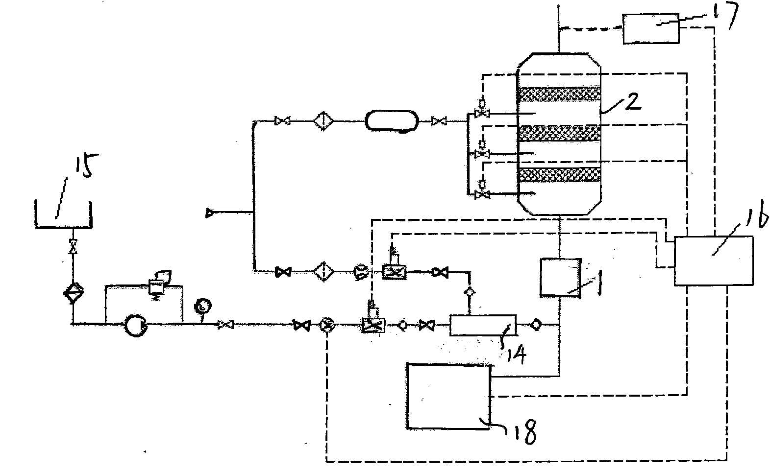
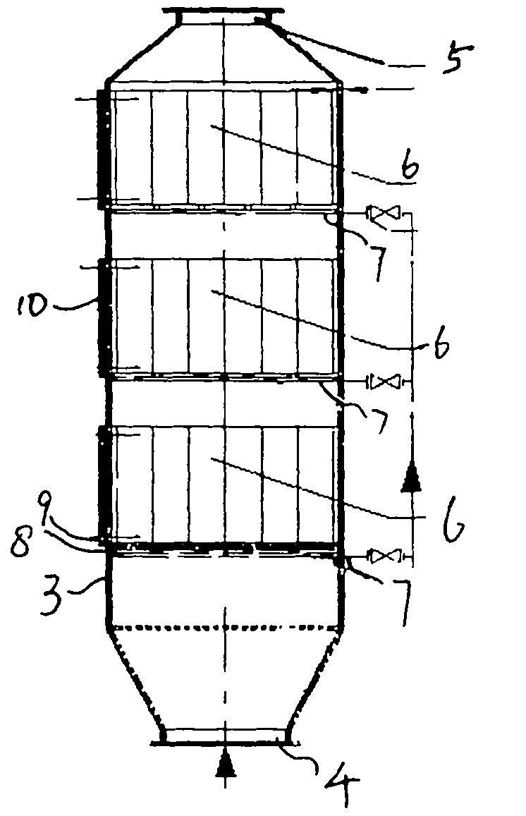
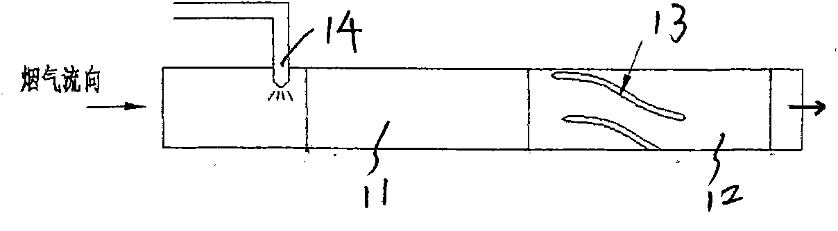
[0042] A marine selective catalytic reduction emission reduction system, including a mixer 1 for mixing a reducing agent with engine flue gas, the mixer is connected to the flue gas inlet of a reactor 2; the reactor includes a shell 3, and a flue gas inlet is arranged on the shell 4. The purified gas outlet 5, and the catalyst module 6 is arranged in the casing; the reducing agent is an aqueous urea solution. The mass concentration of urea in the urea aqueous solution is 39.5-40.5%.

[0043] For a four-stroke supercharged intercooled diesel engine with a speed of 600-1200r / min, the flue gas produced by fuel with a sulfur content of 2 o 5 -TiO 2 , where V 2 o 5 :TiO 2 The mass ratio is: V 2 o 5 :TiO 2 =1:90; For four-stroke supercharged intercooled diesel engines with a rotational speed of 600-1200r / min, the flue gas produced by fuel with a sulfur content greater than 1.5%, and when the temperature of the flue gas is 280-420°C, the catalyst shall be vulcanized Cobalt ox...


PUM


Abstract

The invention discloses a ship selective catalytic reduction emission-reducing system which comprises a mixer, wherein the mixer is used for mixing a reducing agent with engine smoke and is connected with a reactor smoke inlet; a reactor comprises a shell, a smoke inlet and a purified gas outlet are arranged on the shell, and a catalyst module is arranged in the shell; and the reducing agent is an urea aqueous solution. The invention has reasonable structure and high working performance; and when the even mixed gas of the reducing agent and the smoke passes through catalyst in the reactor, NOx in the smoke is selectively reduced into harmless nitrogen (N2) and water (H2O), thereby realizing the standard emission of the NOx.

Description

Technical field: [0001] The invention relates to a marine selective catalytic reduction emission reduction system. Background technique: [0002] The air pollution caused by ships has reached a level that cannot be ignored, and has brought increasingly serious impacts on the internal and external environments of ships, especially in ports, straits and some sea areas with dense routes and high ship traffic. major source of pollution in the area. [0003] The International Maritime Organization (IMO) has proposed three-stage requirements to all flag states for the reduction of NOx emissions from ships. From 2011, the Tier II limit value of NOx emission will be implemented, and the Tier III limit value of NOx emission will be implemented in 2016. Because the NOx limit value stipulated by Tier III cannot be achieved by the technical improvement of the engine itself, and all For NOx emission reduction measures, only the engine exhaust after-treatment device SCR can achieve the ...

Claims


Application Information

Patent Timeline
Patent Type & Authority Applications(China)
IPC IPC(8): F01N3/20F01N3/24B01J23/22B01J27/043B01J29/46B01J23/34
CPCY02T10/24Y02T10/12
Inventor 王德荣
Owner 王德荣
Why Eureka
Try Eureka