[0002] Since the rapid development of magnetic bearing technology in the 1970s, due to the advantages of reducing control current and loss, hybrid magnetic bearings that provide static bias
magnetic flux by permanent magnets and control magnetic flux by DC signals have been developed. It has become a research hotspot, but this type of magnetic bearing cannot meet the requirements of low production cost and low
power consumptionOn the one hand, due to the use of
DC control, the DC power
amplifier is expensive and bulky, and a radial magnetic bearing usually requires four unipolar or two bipolar power
amplifier circuits, which directly leads to the
large size and high cost of the power
amplifier. , which greatly limits the application fields of magnetic bearings, especially in
aerospace and military applications
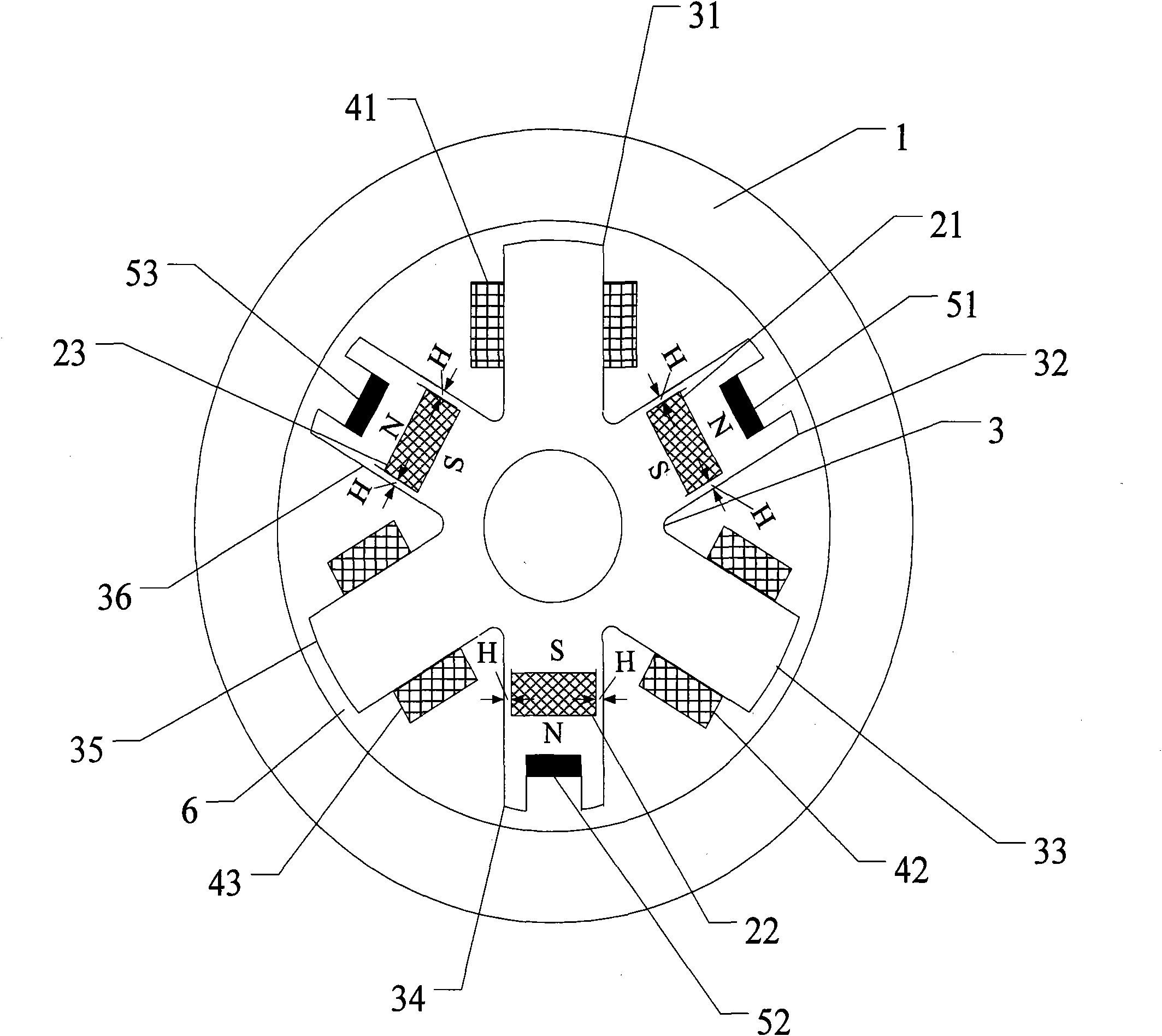
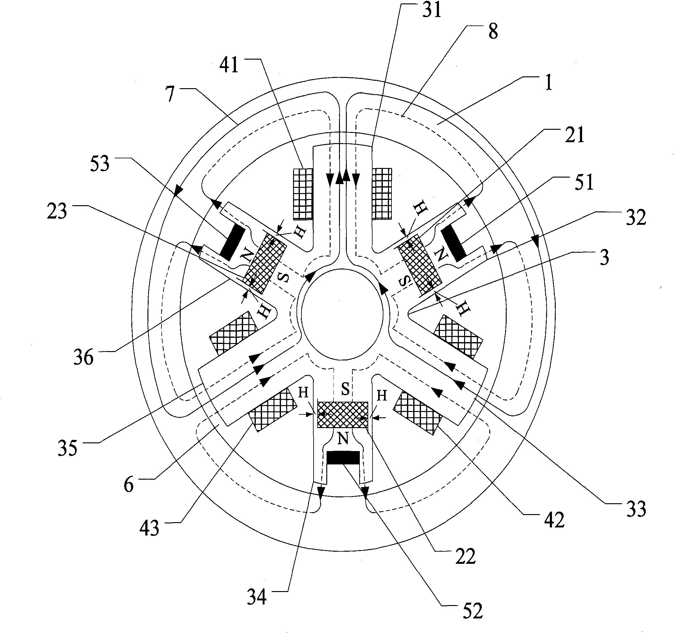
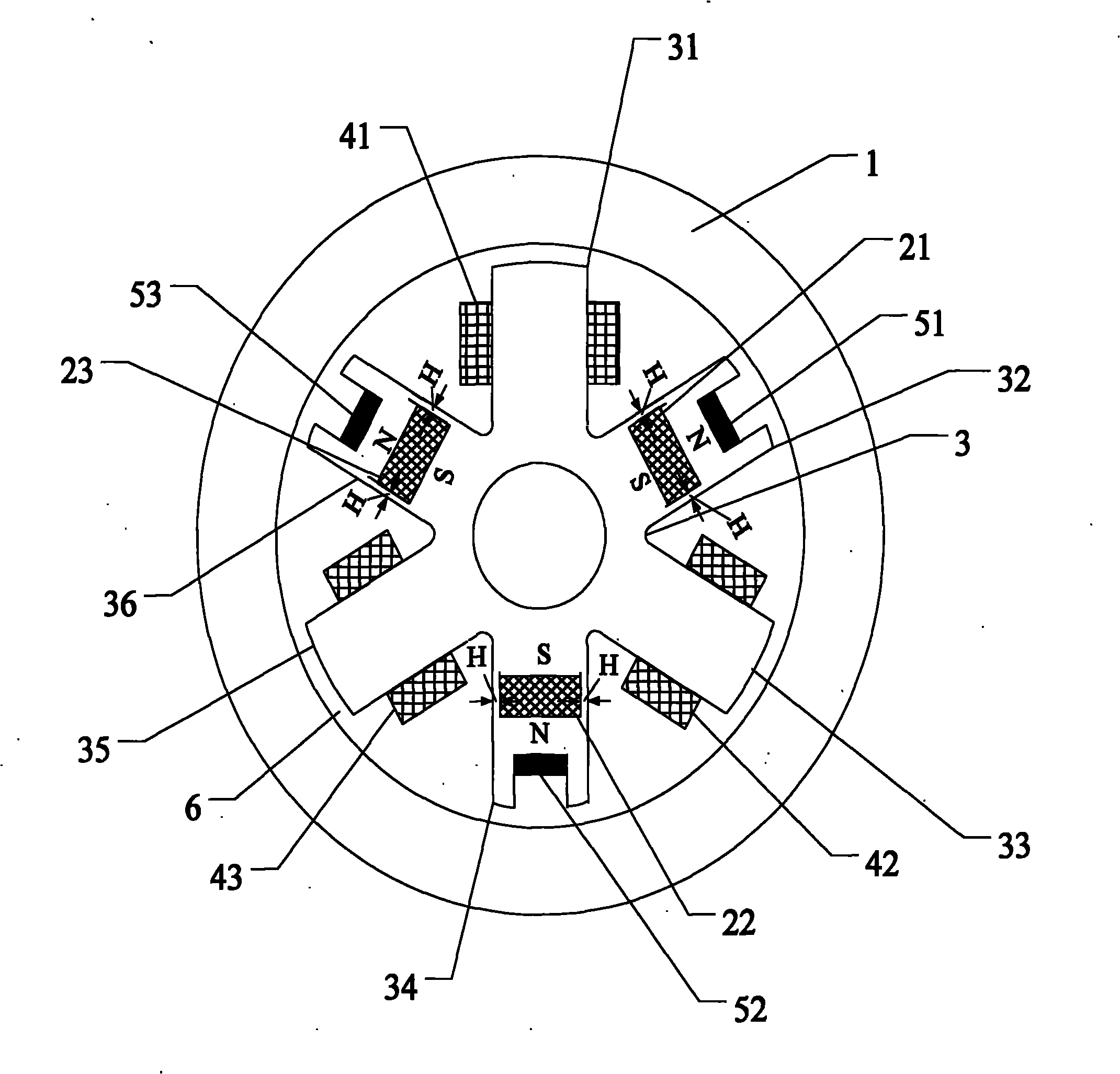
On the other hand, the permanent magnet bias external rotor radial AC hybrid magnetic bearings currently researched internationally are divided into heteropolar and homopolar structures: the magnetic
force lines of the heteropolar structure magnetic bearings are perpendicular to the rotor axis, and the
axial length can be made The magnetic bearings with the same polarity are shorter, but
hysteresis loss will be generated; the magnetic
force lines of the magnetic bearings with the same polarity structure are parallel to the rotor axis, and the generated
hysteresis loss is greatly reduced, but the occupied axial space is relatively large, which cannot meet the needs of
spacecraft such as satellites and space stations. The required small size and light weight are not conducive to the increase of the
critical speed of the rotor
In addition, for some heteropolar magnetic bearings, the permanent magnet is directly placed in the control
magnetic circuit, and the control magnetic flux must pass through the permanent magnet. Since the permanent magnet has a large reluctance, it is necessary to increase the control coil to generate the corresponding control magnetic flux. The
excitation current increases the power consumption of the magnetic bearing, causing serious heating of the coil; some magnetic bearings with the same polarity structure directly connect the permanent magnet to the stator laminated core, so that the permanent
magnetic circuit will lose too much when passing through the stator core The
magnetomotive force greatly weakens the
bearing capacity of the magnetic bearing
[0003] At the Seventh International
Magnetic Bearing Conference in 2000, Redemann C of the Swiss Federal Institute of Technology (ETH) in Zurich published a
test report on the application of a 30kW bearingless sealed pump, and studied a two-degree-of-freedom three-phase AC hybrid magnetic bearing. The bearing directly uses the three-phase
inverter commonly used in the industry to provide the control current, and uses the permanent magnet to provide the static bias
magnetic field, which greatly reduces the size of its power amplifier and reduces the loss, but it still fails to achieve compactness in the overall
system structure. Progress has been made in increasing the
critical speed of the rotor and increasing the capacity of the magnetic bearing
[0004] The existing relevant patent applications are as follows: (1) The patent number is 200510040267.4, and the name is "Permanent
Magnet Bias Radial
Magnetic Bearing". The windings on the two opposite teeth are connected in series, and the
DC drive is adopted. The magnetic bearing of this structure has high power consumption and the cost of the power amplifier is relatively high.
(2) Patent No. 200510086223.5, titled "A Permanent
Magnet Bias Outer Rotor Radial
Magnetic Bearing" uses a single-piece 8-pole heteropolar magnetic bearing structure to control 2
degrees of freedom in the radial direction, and 4 parallel
magnetization The permanent magnet is embedded in the stator core, and a DC power amplifier is used to drive and control four radial control coils. The magnetic bearing of this structure is relatively small in size, but has high power consumption
(3) Patent No. 200510011270.3, titled "A Low
Power Consumption Permanent
Magnet Bias Outer Rotor Radial Magnetic Bearing" In form, it adopts a double-plate eight-pole homopolar magnetic bearing structure to control
two degrees of freedom in the radial direction. And it uses a DC power amplifier to drive and control 8 radial control coils. The magnetic bearing of this structure has a large volume and
higher power consumption than the AC-driven magnetic bearing.

