Flue gas waste heat recovery system based on solution absorption cycle

A flue gas waste heat and recovery system technology, applied in the energy field, can solve the problems of high-grade electric energy consumption, many heat exchange links, and large initial investment, and achieve the effect of small footprint, less heat exchange links, and low investment

Active Publication Date: 2010-12-22
TSINGHUA UNIV +1
View PDF8 Cites 33 Cited by
  • Summary
  • Abstract
  • Description
  • Claims
  • Application Information

AI Technical Summary

Problems solved by technology

[0003] At present, there are patents that use the principle of absorption heat pump to recover waste heat of flue gas by using flue gas as a low-temperature heat source. CN1414287, open date 2003.04.30), patent "heating device for recycling the latent heat of water vapor in gas and oil-fired boiler flue gas" (application number 01136705.9, publication number CN1414288, open date 2003.04.30), although these methods can effectively recycle Waste heat in flue gas, but the system i

Method used


Image

  • Flue gas waste heat recovery system based on solution absorption cycle
  • Flue gas waste heat recovery system based on solution absorption cycle
  • Flue gas waste heat recovery system based on solution absorption cycle

Examples


Embodiment Construction

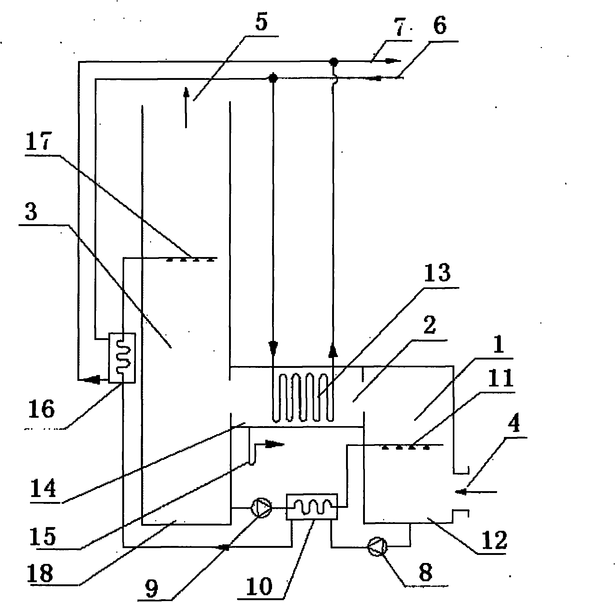
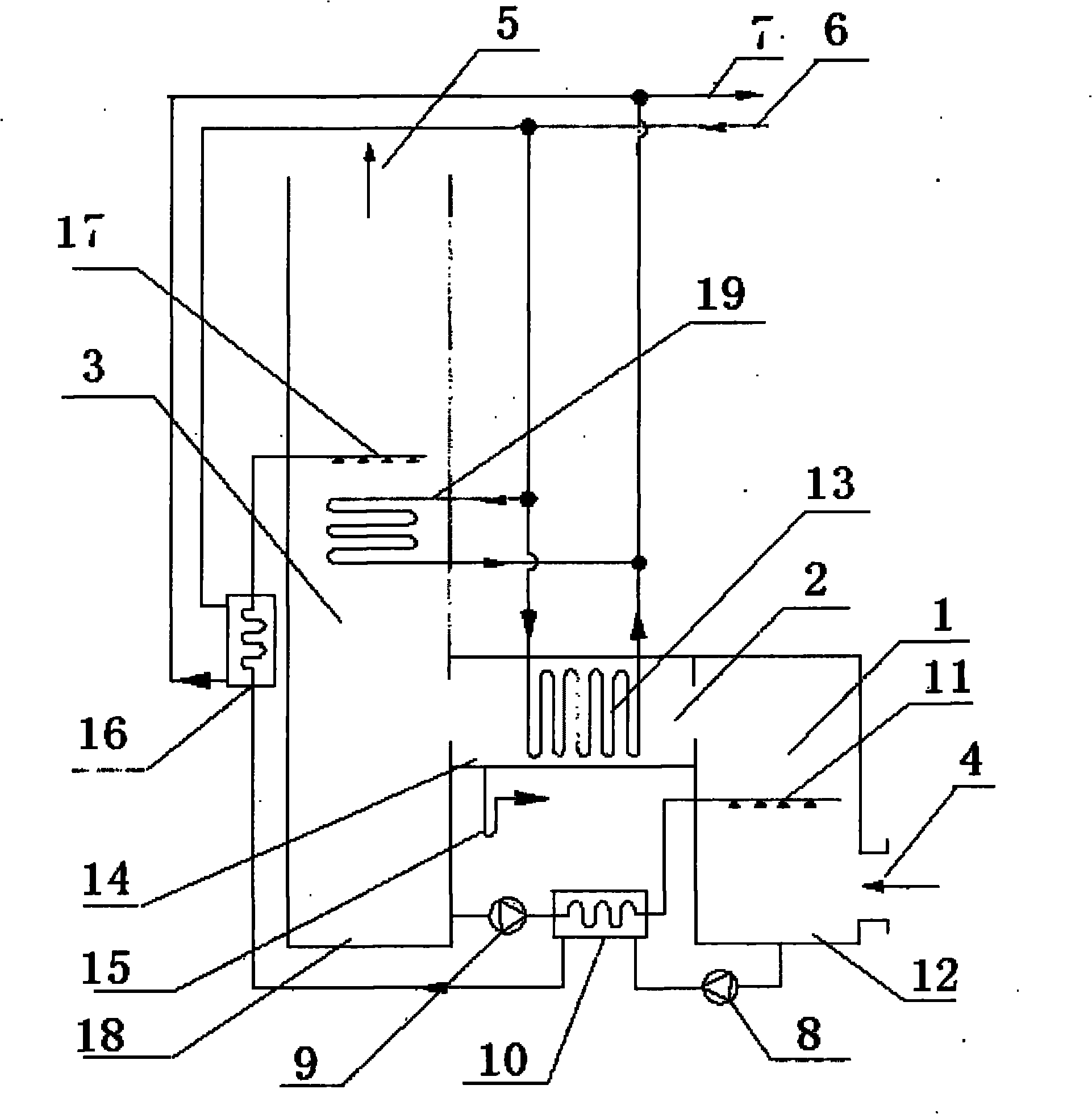
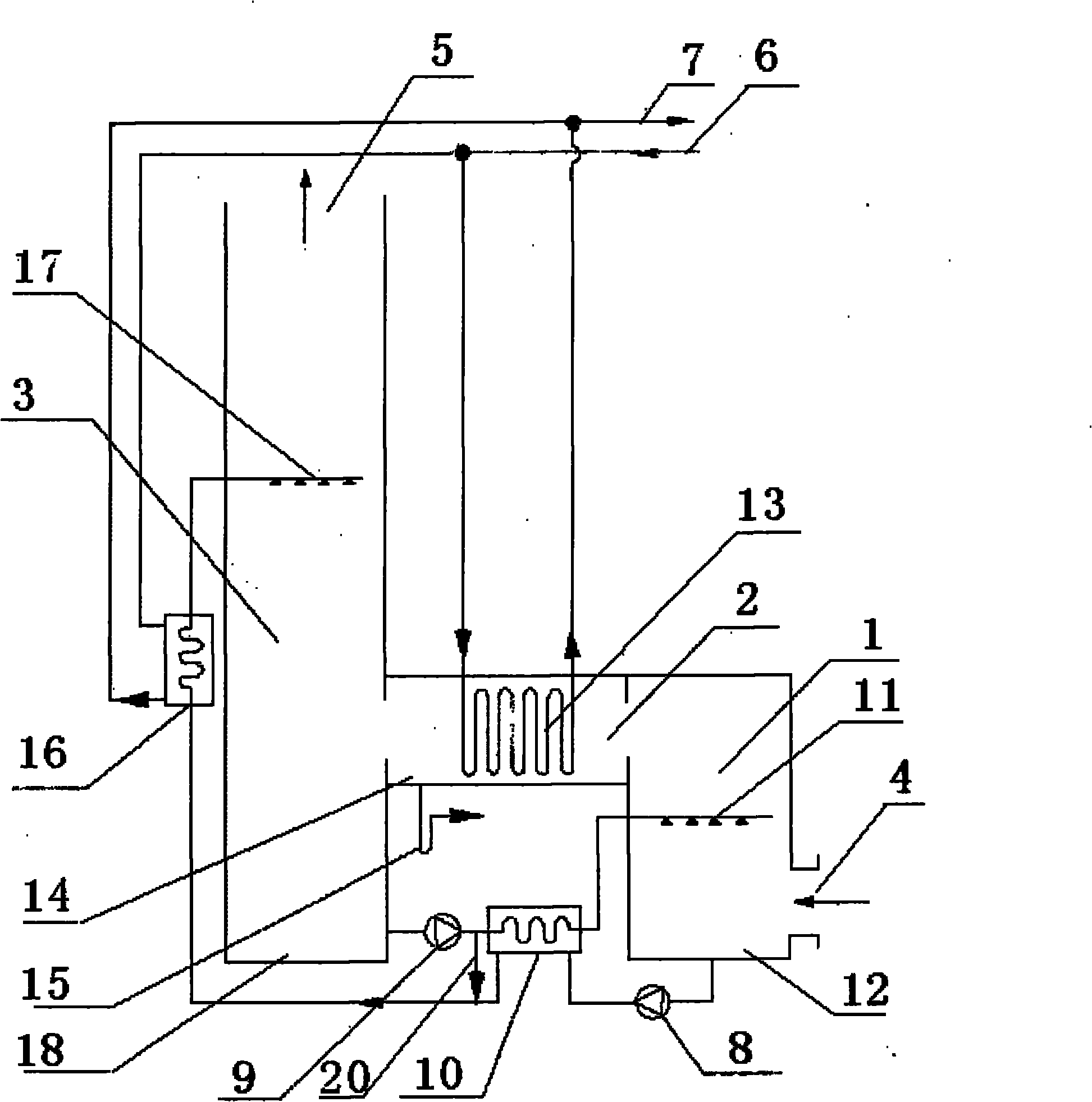
[0036] The present invention is further described below with examples and accompanying drawings.

[0037] figure 1 It is a schematic diagram of a flue gas waste heat recovery system based on a solution absorption cycle. This embodiment is composed of a generator 1, a condenser 2 and an A-level absorber 3. The inlet of the generator 1 is the flue gas inlet 4, and the outlet of the generator 1 is connected to the condenser The inlet of the condenser 2 is connected, the outlet of the condenser 2 is connected with the inlet of the A-level absorber 3, the outlet of the A-level absorber 3 is the flue gas outlet 5, and the generator liquid distribution device 11 is placed horizontally on the top of the generator 1, and the condenser 2 has a cooling coil 13 inside, and the A-level liquid distribution device 17 is horizontally placed on the top of the A-level absorber 3. The inlet of the concentrated solution booster pump 8 is connected to the generator solution tank 12, and the outlet...


PUM


Abstract

The invention belongs to the technical field of energy resources, in particular to a flue gas waste heat recovery system based on solution absorption cycle, which is used for recovering flue gas waste heat and moisture in natural gas. The system consists of a generator, a condenser and an absorber, and the absorber is a one-level absorber or multiple-level serial absorber. High temperature flue gas from a boiler or a gas engine is used for heating a dilute solution in the generator, moisture in the solution is absorbed, the high temperature flue gas becomes high humidity fuel gas, and the dilute solution becomes a concentrated solution. The high humidity fuel gas and cooling water exchange heat in the condenser, the high humidity fuel gas is cooled to below dew point temperature, condensate water is separated out, after being cooled through a solution/solution heat exchanger and a solution/water heat exchanger, the concentrated solution sprays in the absorber and flows downwards, the flue gas flows from bottom to top in the direction opposite to that of the solution, water vapor in the flue gas is absorbed by the solution, and simultaneously, latent heat is discharged and the flue gas is discharged from a chimney. Heating backwater absorbs heat from the condenser, the absorber and the solution/water heat exchanger, and after being heated, the heating backwater can supply heat to a city heating net directly or after being heated by the boiler.

Description

technical field [0001] The invention belongs to the field of energy technology, in particular to a flue gas waste heat recovery system based on a solution absorption cycle. Background technique [0002] Since the main component of natural gas is methane (CH4), which has a high hydrogen content, the flue gas discharged after combustion contains a large amount of water vapor (the volume content is close to 20%), which is the main carrier of the heat of the flue gas. Every 1Nm3 of natural gas can produce 1.55kg of water vapor, and the latent heat is about 3600KJ / Nm3, accounting for about 10% of the low calorific value of natural gas. The effective use of this part of the latent heat of water vapor is economically meaningful. In recent years, many large and medium-sized natural gas boiler rooms, gas-fired thermal power plants, and gas-fired combined heating, power, and cooling systems have appeared in China as heat sources for centralized heating. As high as 200°C or higher, n...

Claims


Application Information

Patent Timeline
IPC IPC(8): F24H4/02F24H8/00F25B27/02F25B15/00F25B15/06
CPCY02B30/625Y02B30/102Y02A30/274Y02B30/00
Inventor 付林王腾张世钢
Owner TSINGHUA UNIV
Why Eureka
Try Eureka