
Refrigerating system for preparing supercooled water ice slurry

A refrigeration system and supercooled water technology, applied in ice making, ice making, refrigerators, etc., can solve problems such as unstable liquid supply control, complex separation systems, and subcoolers that reduce refrigeration cycles and efficiency, and improve heat transfer Efficiency and uniformity of heat transfer, simplification of system flow and control system, effect of reducing the risk of clogging the subcooler

Inactive Publication Date: 2012-10-17
中机西南能源科技有限公司
View PDF2 Cites 0 Cited by
  • Summary
  • Abstract
  • Description
  • Claims
  • Application Information

AI Technical Summary

Problems solved by technology

Water cycle ice slurry requires a subcooler and a cold storage tank. At present, the subcooler uses a tube heat exchanger or a plate heat exchanger. The refrigerant flow channel and water flow channel are not set properly, and the heat transfer efficiency is low and the uniformity is poor. The ice nuclei in the water circulation process often block the supercooler with ice, especially for the refrigeration system that uses gravity liquid supply to produce supercooled ice slurry. Due to the small difference in gravity supply hydraulic pressure, the liquid supply control Unstable, poor uniformity of subcooler temperature control, local temperature is too low to cause ice blockage in the subcooler
Blockage of the subcooler reduces refrigeration cycles and efficiency, while also requiring frequent de-icing and high energy consumption
[0003] In addition, although the lubricating oil contained in the refrigerant is necessary for the compressor, it is unfavorable for the condenser and evaporator (subcooler), and needs to be recovered
At present, separators are used for oil separation, but the separation effect is not ideal
The Chinese patent document with the publication number 1329233A discloses an "ammonia refrigeration system that recycles lubricating oil without loss". The separation effect of lubricating oil is good, but it has a complicated separation system

Method used


Image

  • Refrigerating system for preparing supercooled water ice slurry

Examples


Embodiment Construction

[0015] The present invention will be described in further detail below through specific examples.

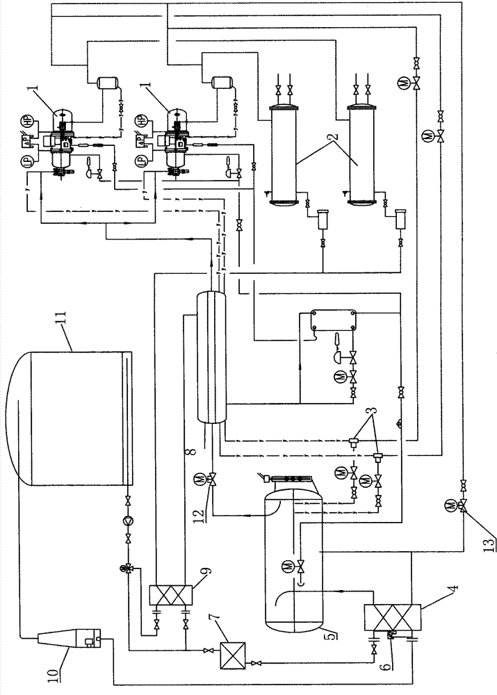
[0016] Such as figure 1 Shown is a refrigeration system for producing supercooled water ice slurry, including a refrigerant circulation system and a water circulation system.

[0017] The water circulation system includes a cold storage tank 11 and a supercooler 4, an ice core filter 7 is installed on the water supply pipeline of the cold storage tank 11 to the supercooler 4, and an ice core filter 7 is installed on the passage for supplying supercooled water to the cold storage tank 11 by the supercooler 4. The supercooling elimination device 10 is also connected in parallel with a bypass valve formed by a preheater 9 and a three-way valve on the water supply line between the cold storage tank 11 and the supercooler 4, which is used to control the inlet water temperature of the subcooler and the For melting and deicing.

[0018] The refrigerant circulation system includes a r...


PUM


Abstract

The invention discloses a refrigerating system for preparing supercooled water ice slurry, which comprises a refrigerant circulating system and a water circulating system. The water circulating system comprises a cold accumulation tank and a supercooler, wherein the supercooler is a plate heat exchanger to directly realize heat exchange between a refrigerant and water, the pressure drop of a refrigerant channel of the plate heat exchanger is no more than 0.2 bar, and the water flow velocity of a water channel of the plate heat exchanger is not more than 1.8m / s. The refrigerant circulating system comprises a refrigeration compressor, a supercooler and a low pressure circulation liquid reservoir, wherein the mounting height of the low pressure circulation liquid reservoir is higher than thesupercooler, and the refrigerant is supplied to the supercooler by using the hydrostatic column pressure of the refrigerant so as to form liquid supply by gravity. The refrigerating system has the advantages of stable work, energy conservation and high refrigerating efficiency.

Description

technical field [0001] The invention relates to a refrigeration system, which is a refrigeration system for preparing supercooled water ice slurry. Background technique [0002] In the current refrigeration system, a cooling method of ice storage is to exchange heat with refrigerant or brine in the subcooler to supercool water to form ice slurry. It usually includes a refrigerant circulation system and a water circulation system, such as the invention patent document of Chinese Patent Application No. 200610051606.3. Water cycle ice slurry requires a subcooler and a cold storage tank. At present, the subcooler uses a tube heat exchanger or a plate heat exchanger. The refrigerant flow channel and water flow channel are not set properly, and the heat transfer efficiency is low and the uniformity is poor. The ice nuclei in the water circulation process often block the supercooler with ice, especially for the refrigeration system that uses gravity liquid supply to produce superc...

Claims


Application Information

Patent Timeline
Patent Type & Authority Patents(China)
IPC IPC(8): F25C1/00F25B47/02F25B49/02
CPCY02P60/85
Inventor 刘楷周国均
Owner 中机西南能源科技有限公司
Learn More