
Involute straight tooth cone gear trimming method

A technology of straight bevel gears and bevel gears, which is applied in program control, instrumentation, electrical and digital data processing, etc., can solve problems such as the inability to realize the processing of modified straight bevel gears, and achieve outstanding substantive characteristics, compensation for deformation, and significant improvement. effect of progress

Inactive Publication Date: 2011-01-05
UNIV OF JINAN
View PDF5 Cites 48 Cited by
  • Summary
  • Abstract
  • Description
  • Claims
  • Application Information

AI Technical Summary

Problems solved by technology

However, these methods cannot realize the processing of modified straight bevel gears, and corresponding follow-up processing is required to realize the modification of bevel gears

Method used


Image

  • Involute straight tooth cone gear trimming method
  • Involute straight tooth cone gear trimming method
  • Involute straight tooth cone gear trimming method

Examples


Embodiment Construction

[0023] In order to clearly illustrate the technical features of the solution, the solution will be described below through a specific implementation mode combined with the accompanying drawings.

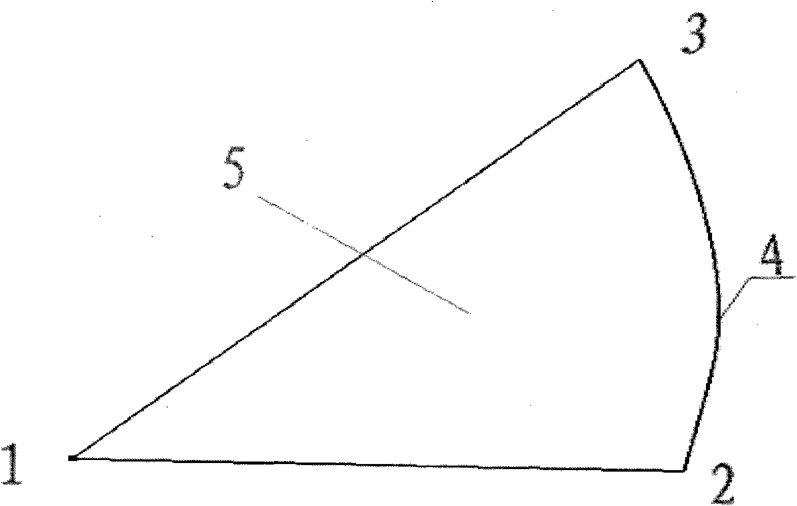
[0024] Read the coordinates of the big-end involute of the bevel gear calculated by the mathematical software Matlab into the three-dimensional modeling software SolidWorks to generate the big-end spherical involute, such as figure 1 shown. Curve 4 is the big-end spherical involute, which connects the two ends 2 and 3 of the involute and the coordinate origin 1 to form a closed interval, and the spherical involute surface 5 is formed by filling the curved surface.

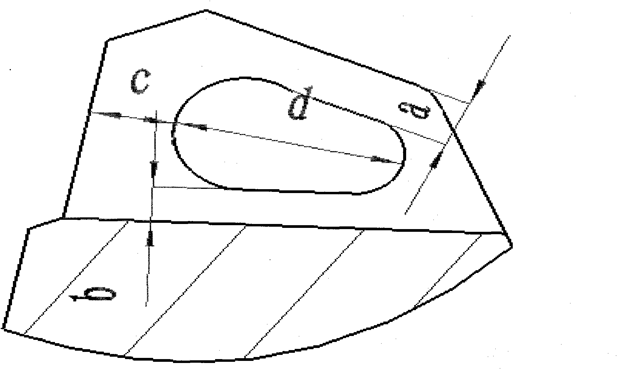
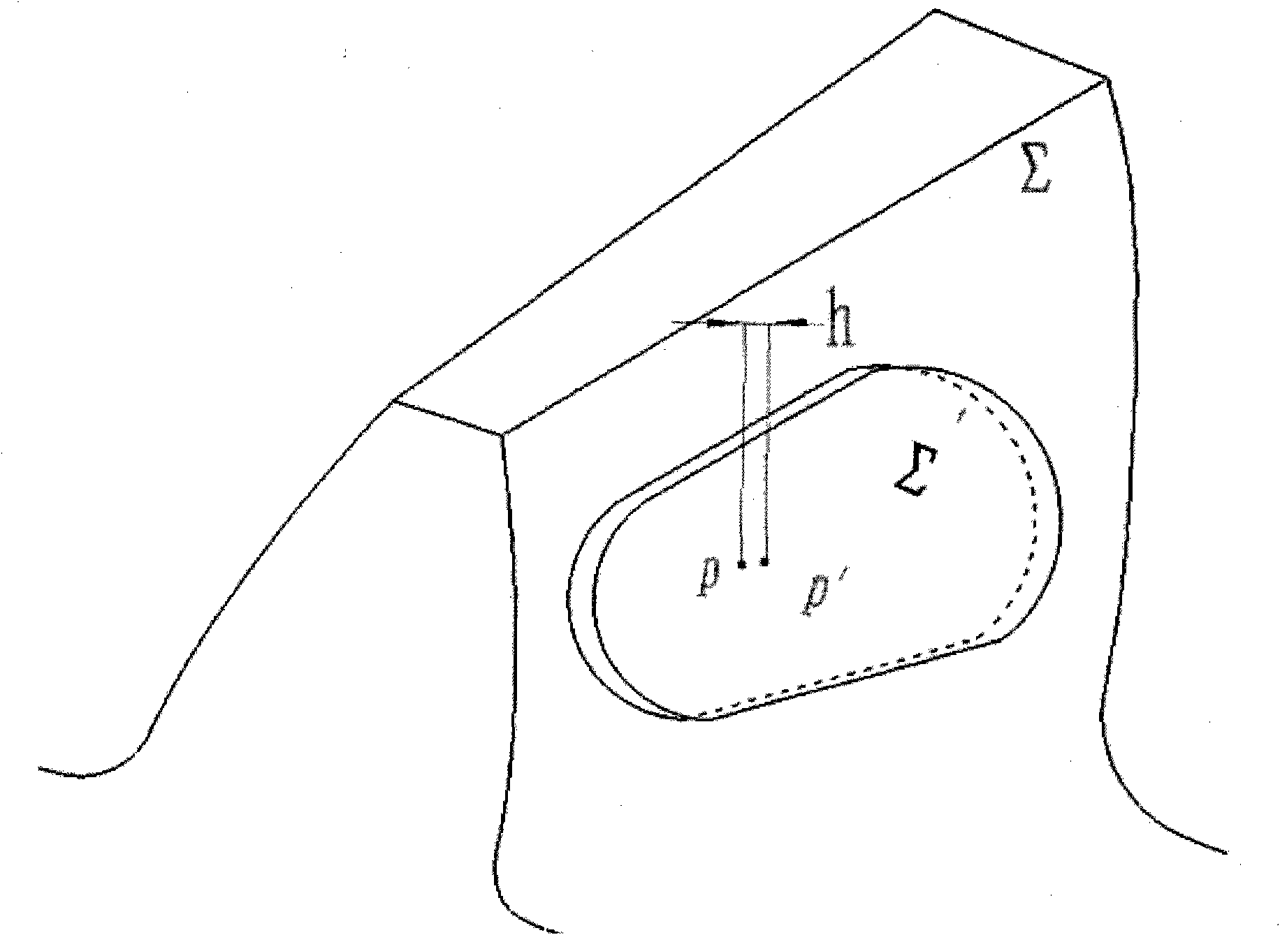
[0025] On the half-section of the gear tooth, make a modified profile with equal distances in the tooth direction, such as figure 2 shown. The profile length is d along the tooth width direction, a is the distance from the tooth top along the tooth height direction, b is the distance from the tooth root, and the distan...


PUM


Abstract

The invention provides a technical scheme, in particular an involute straight tooth cone gear trimming method. The method comprises the following steps of: determining a tooth trimming position, a trimming quantity and a tooth profile quantity; solving for a spherical space involute Decare coordinate equation; generating a spherical involute in three-dimensional modeling software, forming a spherical involute plane through curve filling, and realizing straight tooth cone gear solid modeling on the basis of the spherical involute; forming a tooth trimming profile on the central cross section of the gear, and isometrically stretching the profile to the tooth surface to realize tooth isometric trimming; carrying out tooth top arc trimming on the tooth profile; and converting a trimming gear model into a digital control code imported into a digital control machine tool to realize the processing of the trimming cone gear. The invention better controls the stress distribution of the gear through controlling the position and the trimming quantity of the isometric trimming so as to compensate the deformation of the gear and reduces the sensitivity of a cone gear pair to errors and load changes as well as improves the transmission precision of the cone gear pair, reduces the vibration and the noise and prolongs the service life of the gear.

Description

technical field [0001] The invention relates to a gear manufacturing method, in particular to a modification method of an involute spur bevel gear. Background technique [0002] The tooth profile of the standard involute bevel gear is a space spherical involute. However, because the involute bevel gear bears a wide range of loads, and is subject to manufacturing and installation errors, bending and torsion deformation of the shaft system, wheel load, etc. The complex factors such as tooth contact deformation and bearing clearance make the tooth profile deviate from the spherical involute in theoretical space, resulting in reduced transmission accuracy and increased vibration and noise. Through gear modification, an equidistant curved surface is processed on the standard tooth surface. At this time, the meshing of the gear teeth occurs on the equidistant curved surface, which effectively controls the stress distribution of the gear teeth, and the deformation of the gear teeth...

Claims


Application Information

Patent Timeline
IPC IPC(8): G05B19/4097B23P6/00G06F17/50
Inventor 崔焕勇杨东田希杰
Owner UNIV OF JINAN
Learn More