Ultra-low temperature freezer, refrigeration system and vacuum apparatus

An ultra-low temperature refrigeration and refrigerant technology, applied in the field of refrigeration systems, vacuum devices, and ultra-low temperature refrigeration devices, can solve the problems of insufficient buffer tank capacity, reduced cooling efficiency, prolonged cooling time, etc., to prevent gas refrigerant from staying in the buffer tank. The effect of reducing cooling efficiency and reducing equipment cost

Inactive Publication Date: 2011-01-12
SHIN MEIWA IND CO LTD
View PDF4 Cites 4 Cited by
  • Summary
  • Abstract
  • Description
  • Claims
  • Application Information

AI Technical Summary

Problems solved by technology

For this reason, the flow rates of the refrigerant flowing to the main cooler and the subcooler are set to be equal to each other as described above. However, if the amount of liquid refrigerant flowing to the secondary side of the subcooler is small, the flow rate of the gas refrigerant on the primary side will be reduced. Insufficient cooling, which leads to a decrease in the flow rate of liquid refrigerant liquefied by the subcooler and a reduction in the cooling efficiency of the main cooler
As a result, the load of the cooling object cooled by the main cooler fluctuates, or the cooling object whose load fluctuates cannot be cooled stably, or the cooling required to cool the cooling object from normal temperature to ultra-low temperature by the main cooler The problem of extended time
[0018] (2) Next, stop the normal operation of the refrigerating device, and supply the blown gas from the compressor to the cooler through the defrosting circuit to defrost the cooler. If the oiler removes the refrigeration oil, the refrigeration oil will flow into the defrosting circuit, supply it to the cooler in the ultra-low temperature state, and freeze in the refrigerator.
[0019] (3) Again, if the refrigerating machine oil etc. are supplied to the cooler and solidified in the cooler, then even if the refrigerating machine oil passes through the cooler when the temperature of the cooler is raised, the refrigerating machine oil flowing out of the cooler is equivalent to the ultra-low temperature state It is supplied to the heat exchanger, and the refrigerating machine oil will also solidify in the heat exchanger. It takes time to eliminate the solidification of the refrigerating machine oil, etc., resulting in the problem that the defrosting operation time is prolonged.
However, in this method, a pressure loss occurs due to the flow resistance of the mixed refrigerant, and there is another problem that the cooling efficiency is lowered.
[0021] (4) Also, in recent years, in order to improve the cooling capacity of refrigeration equipment, low-boiling refrigerants that are kept in a gaseous state during operation and shutdown have been widely used. Therefore, the problem of insufficient capacity of the buffer tank has arisen.
[0025] In this way, it is difficult to cool the cooler to the ultra-low temperature level in a short time in the conventional pressure reducer circuit configuration

Method used


Image

  • Ultra-low temperature freezer, refrigeration system and vacuum apparatus
  • Ultra-low temperature freezer, refrigeration system and vacuum apparatus
  • Ultra-low temperature freezer, refrigeration system and vacuum apparatus

Examples


Embodiment approach 1

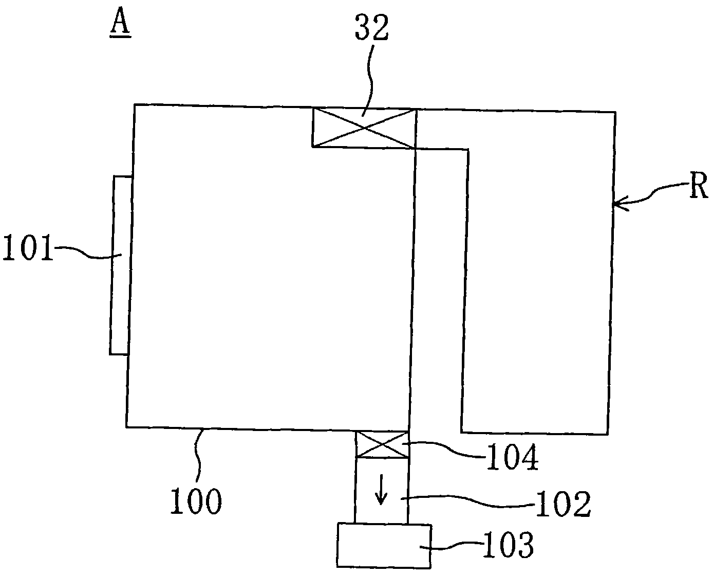
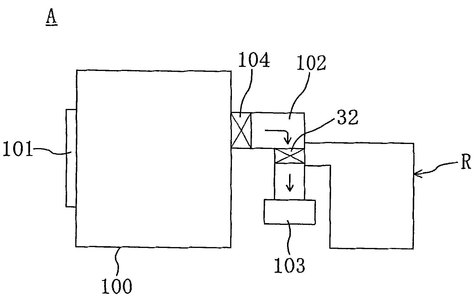
[0187] figure 1 , is a layout plane schematically showing the vacuum film forming apparatus A of the vacuum film forming apparatus according to the embodiment of the present invention. Figure 1 example. 100 is a vacuum container in which a substrate (not shown) (also referred to as a wafer) is deposited in a vacuum state. On the vacuum vessel 100, an entrance (not shown) opened and closed by the opening and closing door 101 is provided. With the opening and closing door 101 opened, the substrate to be filmed is sent into the vacuum vessel 100, or the film-forming substrate The substrate is taken out from the vacuum vessel 100. At the connecting part of the communication pipe 102 and the vacuum container 100, a switching slide valve 104 is provided to make the two communicate or cut off by opening and closing. When the opening and closing door 101 is closed and the slide valve 104 is opened, the vacuum pump 103 The operation brings the inside of the vacuum container 100 int...

Embodiment approach 2

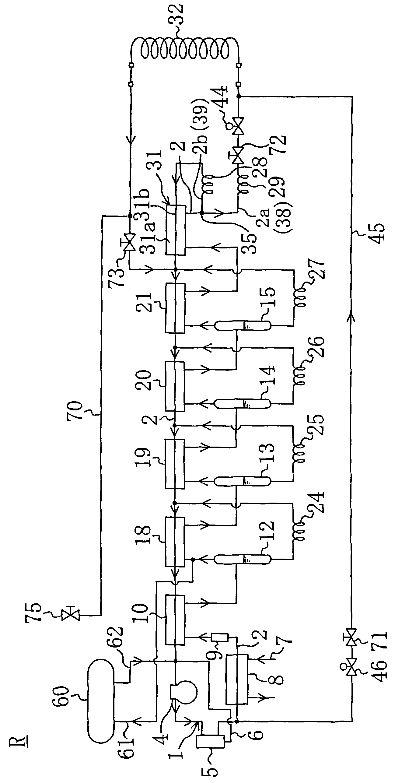
[0215] Image 6 represents Embodiment 2 of the present invention (and, in each of the following embodiments, the same as Figure 1 to Figure 5 The same parts are marked with the same symbols and their detailed descriptions are omitted). In Embodiment 1, the sub-refrigerant circuit 39 is positioned lower than the main refrigerant circuit 38 , and more liquid refrigerant flows into the secondary side 31 b of the subcooler 31 than into the cryocoil 32 . In this regard, in this embodiment, when the sub-refrigerant circuit 39 and the main refrigerant circuit 38 are at the same height, the cross-sectional area of ​​the sub-refrigerant circuit 39 is made larger than that of the main refrigerant circuit 38 .

[0216] That is, in this embodiment, different from Embodiment 1, the collective part 35a of the branch pipe 35, the main side branch pipe 35b and the main refrigerant pipe 2a connected thereto, the secondary side branch pipe 35c of the branch pipe 35 and the branch pipe 35c con...

Embodiment approach 3

[0223] Figure 7 and Figure 8 Embodiment 3 is shown, and is a combination of technical matters of Embodiment 1 and Embodiment 2. That is, in this embodiment, as in Embodiment 1 above, the main side branch pipe 35b and the secondary side branch pipe 35c of the branch pipe 35, the secondary side branch pipe 35c is arranged so as to be located at a position below the main side branch pipe 35b along an approximately vertical direction. The sub-side branch pipe 35c and the sub-refrigerant pipe 2b connected thereto are disposed in parallel vertically, and are arranged at a height lower than the main-side branch pipe 35b and the main refrigerant pipe 2a connected thereto. Meanwhile, in Embodiment 2, the main refrigerant pipe 2a connected to the main side branch pipe 35b of the branch pipe 35 uses a pipeline having a smaller diameter than the sub refrigerant pipe 2b connected to the sub side branch pipe 35c, and the cross section of the sub refrigerant circuit 39 The area is larger...


PUM


Abstract

An ultralow temperature refrigerator (R) using a mixed refrigerant containing a plurality of kinds of refrigerants having different boiling points. The refrigerator (R) comprises a main refrigerant circuit (38) provided with a criocoil (32) and a capillary tube (29) and a sub-refrigerant circuit (39) the upstream end of which is branched and connected to the upstream end of the main refrigerant circuit (38) and which is provided with a capillary tube (28). In order to ensure the flow of the liquid refrigerant for a supercooler (31) and to enhance the cooling eficiiency of the criocoil (32), the height of the sub-refrigerant circuit (39) is less than the height of the main refrigerant circuit (38). The flow of the refrigerant in a gas-liquid mixed state discharged from the primary side (31a) of the supercooler (31) and flowing into the sub-refrigerant circuit (39) is greater than the flow into the main refrigerant circuit (38), so that the flow of the liquid refrigerant into the sub-refrigerant circuit (39) is increased more than the flow into the main refrigerant circuit (38).

Description

[0001] This application is a divisional application for the divisional application 200910118136.1 filed on March 2, 2009 with the title of invention "ultra-low temperature freezing device and vacuum device" technical field [0002] The present invention relates to an ultra-low temperature freezing device, a freezing system and a vacuum device for generating ultra-low temperature cooling capacity. Background technique [0003] So far, as a refrigeration system for generating ultra-low temperature below -100°C, as shown in Patent Documents 1, 2, and 3, a non-azeotropic mixed refrigerant formed by mixing a plurality of refrigerants with different boiling point temperatures is enclosed in a refrigerant circuit. Methods for ultra-low temperature freezers are known. This kind of ultra-low temperature freezing device, such as the moisture installed in the vacuum tank of the vacuum film forming device for manufacturing substrates (wafers), etc., is removed by freezing to improve the...

Claims


Application Information

Patent Timeline
Patent Type & Authority Applications(China)
IPC IPC(8): F25B9/10F25B43/02F25B47/02F25B49/02B65D81/18F26B5/06F25B9/00
CPCF25B45/00F25B39/028F25B9/006F25B2500/26F25D2400/30F25B49/005F25D11/04F25B2700/1931F25B2500/01F25B41/42
Inventor 高桥正幸八木昌文清水宽正友泽章池田昌彦盐野真士
Owner SHIN MEIWA IND CO LTD
Why Eureka
Try Eureka