Low-ratio biomass circulating fluidized bed boiler and combustion method thereof

A technology of circulating fluidized bed and biomass fuel, which is applied in the direction of fluidized bed combustion equipment, combustion method, fuel burned in a molten state, etc., and can solve tempering and output drop, slagging on the grate, feeding difficulties, etc. problems, achieve the effects of reducing power consumption, improving combustion efficiency, and prolonging residence time

Inactive Publication Date: 2011-01-19
湖南博茂节能环保科技有限公司
View PDF6 Cites 38 Cited by
  • Summary
  • Abstract
  • Description
  • Claims
  • Application Information

AI Technical Summary

Problems solved by technology

[0006] The purpose of the present invention is to provide a low-magnification biomass circulating fluidized bed boiler and its combustion method, in order to solve the ab

Method used


Image

  • Low-ratio biomass circulating fluidized bed boiler and combustion method thereof
  • Low-ratio biomass circulating fluidized bed boiler and combustion method thereof
  • Low-ratio biomass circulating fluidized bed boiler and combustion method thereof

Examples


specific Embodiment approach 1

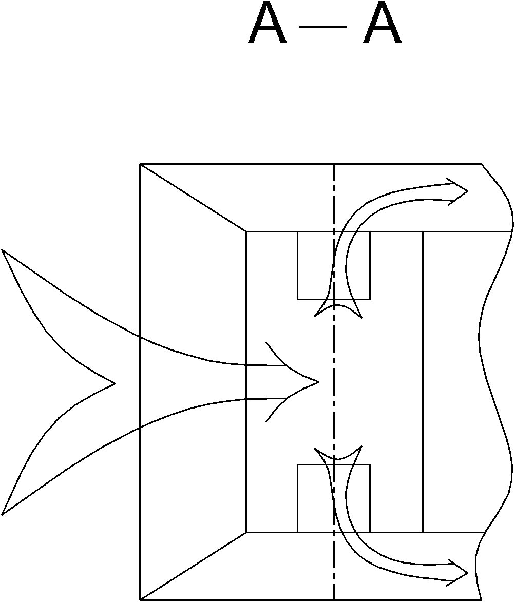
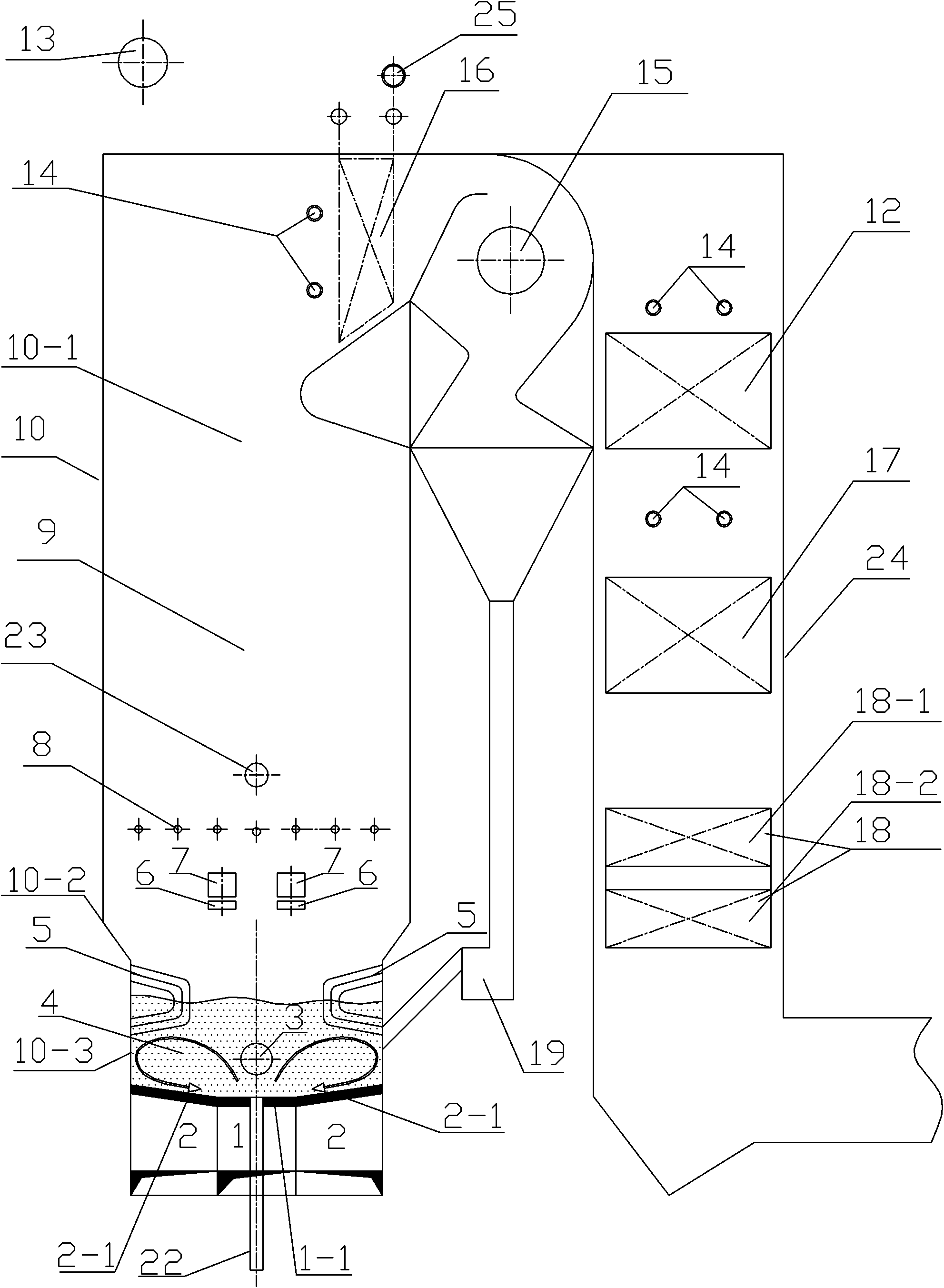
[0023] Specific implementation mode one: as Figure 1~2 As shown, the low-magnification biomass circulating fluidized bed boiler in this embodiment includes a furnace body 10, a tail shaft flue 24, an economizer 17, an air preheater 18, a furnace door 3, a buried pipe 5, and a biomass fuel Feed port 7, secondary air port 8, bed material feeding pipe 23, boiler drum 13, soot blower 14, medium-temperature gas-cooled cyclone separator 15, feeder 19, first-stage desuperheater 20 and second-stage Desuperheater 21, the boiler also includes middle air chamber 1, side air chamber 2, middle air distribution plate 1-1, side air distribution plate 2-1, slag discharge pipe 22, material spreading tuyere 6, top middle temperature screen type Superheater 11, high-temperature convection superheater 12 and low-temperature convection superheater 16; the furnace body 10 is surrounded by membrane water-cooled walls, and the furnace body 10 is composed of upper furnace body 10-1, transition Secti...

specific Embodiment approach 2

[0033] Specific implementation mode two: as image 3 As shown, the low-magnification biomass circulating fluidized bed boiler described in this embodiment cancels the panel superheater, and arranges the low-temperature superheater 16 before the furnace outlet and the medium-temperature gas-cooled cyclone separator 15, and the high-temperature superheater 12 is placed in the tail shaft In the upper part of the flue, the desuperheater 25 (water spray or surface desuperheater) is arranged above the low temperature superheater 16 . The saturated steam is introduced from the drum 13 into the medium-temperature steam-cooled cyclone separator 15 , and then enters the low-temperature superheater 16 , the desuperheater 25 and the high-temperature convective superheater 12 . The material of the high-temperature convection superheater 12 is TP347H, and the material of the low-temperature superheater 16 is 20g (medium temperature and medium pressure) or 20G (sub-high temperature and sub-h...

specific Embodiment approach 3

[0034] Specific implementation mode three: as Figure 1~3 As shown, the combustion method of the low rate biomass circulating fluidized bed boiler described in this embodiment and the specific embodiment 1 or 2 for burning biomass fuel is realized according to the following steps:

[0035] Step 1, adding bed material with an average particle size of 0.6-0.8 mm from the bed material feeding pipe 23 to the furnace of the furnace body 10;

[0036] Step 2. Adopt the negative pressure feeding method: the biomass fuel is sent to the biomass fuel feeding port 7 through the feeder, and the biomass fuel is sucked into the furnace by its own weight and the negative pressure in the furnace. Under the action of the sowing wind, the heavier biomass fuel is blown by the sowing wind during the falling process, and is dispersed to the lower dense-phase zone 4 for combustion, and the fine debris is blown to the upper dilute-phase zone 9 by the flue gas for combustion;

[0037] Step 3, using a...


PUM

PropertyMeasurementUnit
Particle sizeaaaaaaaaaa
The average particle sizeaaaaaaaaaa

Abstract

The invention relates to a low-ratio biomass circulating fluidized bed boiler and a combustion method thereof, relating to a circulating fluidized bed boiler and a combustion method thereof and solving the problems of difficult feeding, grate slagging, bed material coking, tempering and output reduction, and the like existing in the operation of traditional grate furnaces and circulating fluidized bed boilers. A middle air chamber corresponds to the middle of a dense-phase area at the lower part, lateral grid plates are arranged between a lateral air chamber and the dense-phase area at the lower part, and a medium-temperature steam-cooled cyclone separator is arranged at the joint between a flue shaft at the tail part and a health outlet of a boiler body, respectively communicated with the flue shaft and the health outlet and communicated with the dense-phase area at the lower part through a material returner. The method adopts a negative-pressure feeding manner so that the fluidization air velocity of a high-speed area of the dense-phase area at the lower part is 4-5 m/s, the fluidization air velocity of a low-speed area is 1.5-2.0 m/s, the temperature of the dense-phase area at the lower part is 650-780 DEG C, and the material circulation ratio is below 10. The invention is suitable for the biomass circulating fluidized bed boiler for an electric power plant.

Description

technical field [0001] The invention relates to a circulating fluidized bed boiler and a combustion method thereof, in particular to a low rate circulating fluidized bed boiler burning biomass fuel and a combustion method thereof. Background technique [0002] my country's "Renewable Energy Medium and Long-Term Development Plan" proposes that by 2020, the installed capacity of biomass power generation will reach 24 million kilowatts. The next ten years will be a period of rapid development of the biomass direct combustion power generation industry. get flourishing. [0003] At present, the main furnace types of domestic biomass power generation boilers are water-cooled vibrating grate furnaces imported from Denmark and domestic water-cooled vibrating grate furnaces, chain grate furnaces, reciprocating grate furnaces (they are collectively referred to as layer-fired boilers) and circulating fluidized bed boilers. [0004] The layer fired boiler has simple structure, convenien...

Claims


Application Information

Patent Timeline
IPC IPC(8): F23C10/10F23C10/20F23C10/22
Inventor 别如山杨文
Owner 湖南博茂节能环保科技有限公司
Why Eureka
Try Eureka