Silicon micro-resonant accelerometer

An accelerometer and resonant technology, applied in the field of micro-inertial sensors, can solve the problems of not completely eliminating the influence of ambient temperature on device performance, high temperature coefficient of speedometer frequency, and inability to recognize acceleration signals, etc., to reduce cross-axis sensitivity , reduce the temperature coefficient, improve the stability and impact resistance

Active Publication Date: 2011-02-02
NANJING UNIV OF SCI & TECH
View PDF3 Cites 25 Cited by
  • Summary
  • Abstract
  • Description
  • Claims
  • Application Information

AI Technical Summary

Problems solved by technology

The temperature experiment in the full temperature range found that the temperature coefficient of the accelerometer frequency reaches 160Hz / °C, and the temperature coefficient of the scale factor is 0.67% / °C. The differential detection method does not completely eliminate the influence of the ambient temperature on the performance of the device.
This is because the resonant frequencies of the two resonators are not exactly equal due to processing errors, and the thermal stress acting on the two resonators is also different, so the influence of thermal stress cannot be eliminated by differential detection.
The two resonators of this structure are directly connected to the fixed base, and the processing residual stress and thermal stress have a great influence on the resonant frequency, so that the frequency temperature coefficient of the speedometer is relatively large
In addition, during the test, it was found that the accelerometer has a large electrical coupling. When the resonant frequencies of the two resonators are similar, adjacent frequency interference will occur, so that the applied acceleration signal cannot be identified.

Method used


Image

  • Silicon micro-resonant accelerometer
  • Silicon micro-resonant accelerometer
  • Silicon micro-resonant accelerometer

Examples


Embodiment Construction

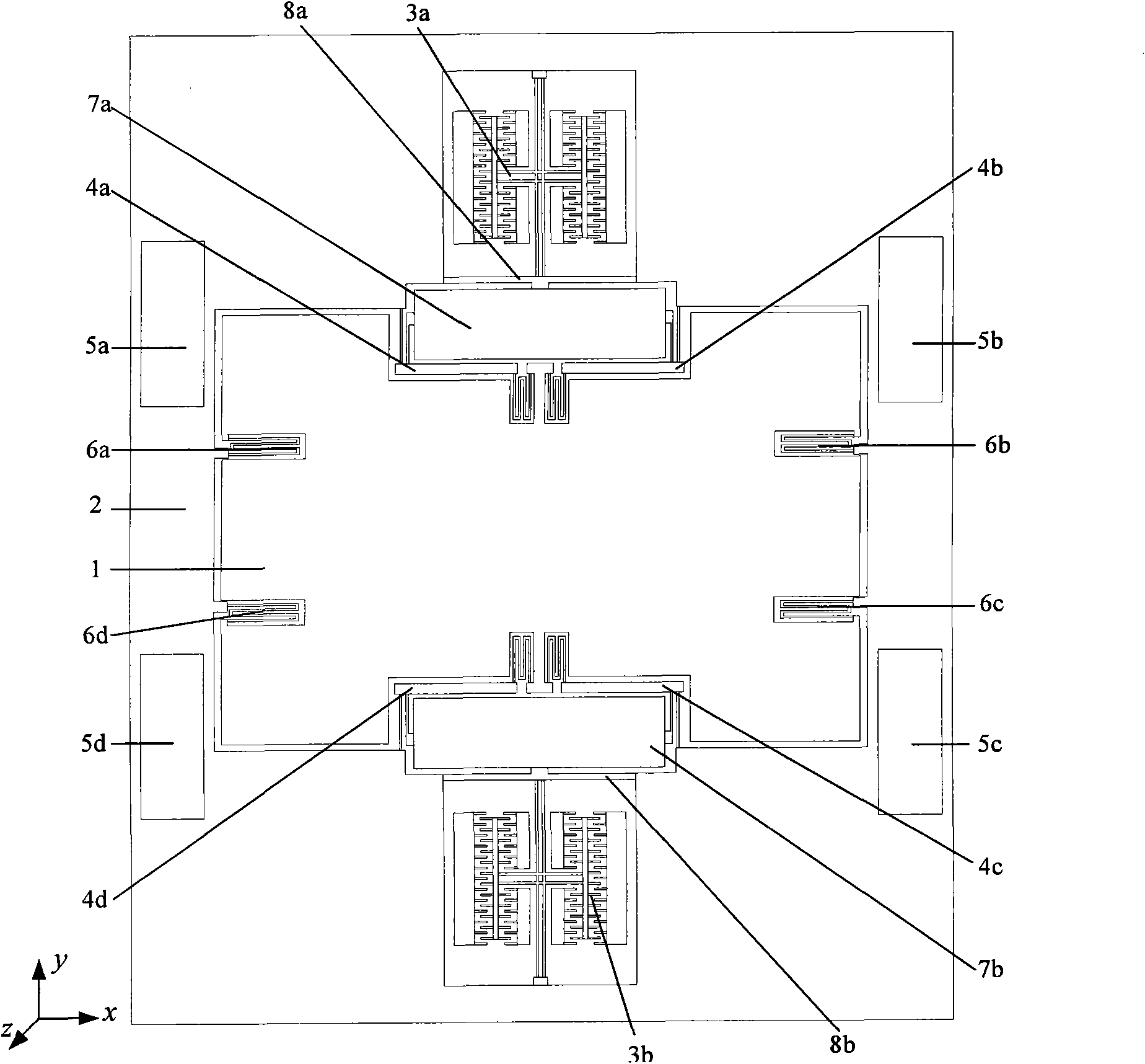
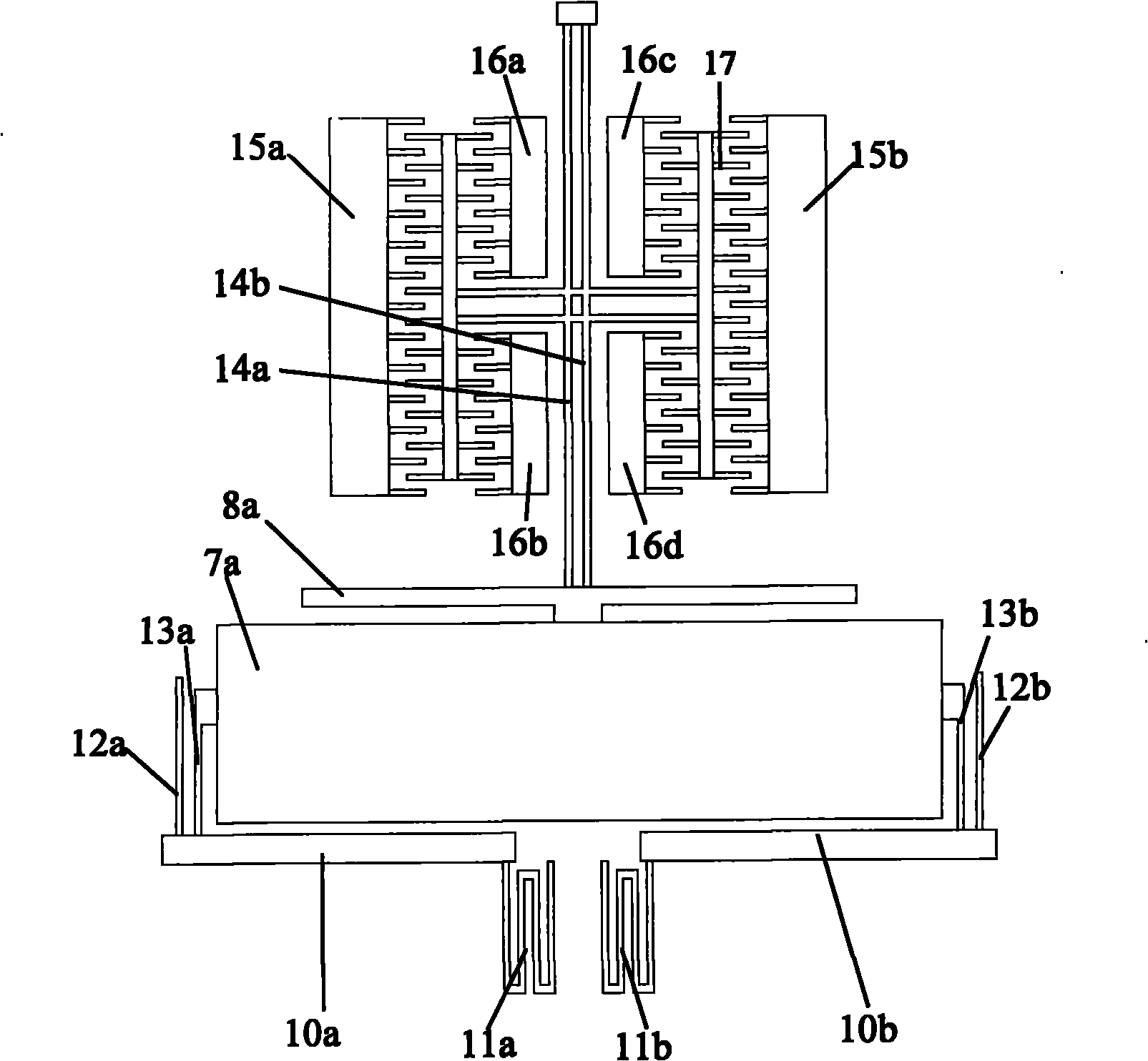
[0011] to combine figure 1 , the present invention is based on the resonant silicon micro-accelerometer, which is used to measure the measuring instrument parallel to the base level. It consists of upper and lower layers. signal leads on the substrate. The mechanical structure of the accelerometer consists of a mass block 1, an outer frame 2, a pair of resonators 3a, 3b and four identical primary lever amplification structures 4a, 4b, 4c, 4d, two rigid rods 7a, 7b and two Guide mechanism 8a, 8b is composed of mass block 1, two resonators 3a, 3b, four primary lever amplification mechanisms 4a, 4b, 4c, 4d, two rigid rods 7a, 7b and two guide mechanisms 8a, 8b Located in the outer frame 2. The mass block 1 is arranged in the middle of the accelerometer structure, and the first and second resonators 3a, 3b are symmetrically arranged at the upper and lower ends of the mass block 1. One end of the two resonators 3a, 3b is connected to the outer frame 2, and the first The other en...


PUM


Abstract

The invention discloses a silicon micro-resonant accelerometer which comprises an upper layer and a lower layer, wherein the upper layer is an accelerometer mechanical structure manufactured on a single-crystal silicon wafer, the lower layer is a signal lead manufactured on a glass substrate, the accelerometer mechanical structure comprises a mass block, an outer frame, two resonators, four primary leverage amplification mechanisms, two rigid rods and two guide mechanisms, a first resonator and a second resonator are symmetrically arranged at the upper side and the lower side of the mass block, one end of either resonator is connected with the outer frame, and the other end is connected with the guide mechanism; and the mass block is connected with the outer frame by four multi-folded beams, and the outer frame enables the mechanical structure part at the upper layer to suspend above the glass substrate part at the lower part by means of four fixed bases which are symmetrical with the center of the mass block. The invention greatly reduces the influence of residual machining stress and heat stress produced by the temperature change of the working environment on the vibration frequency of the structure, improves the stability of the resonant frequency of the resonator and reduces the temperature coefficient of frequency.

Description

technical field [0001] The invention belongs to micro-inertia sensor technology in MEMS, in particular to a silicon micro-resonance accelerometer. Background technique [0002] Silicon micro accelerometer is a typical MEMS inertial sensor. Its research began in the early 1970s, and there are various forms such as capacitive, piezoelectric, piezoresistive, thermal convection, tunnel current and resonance. The unique feature of the silicon microresonant accelerometer is that its output signal is a frequency signal, and its quasi-digital output can be directly used in complex digital circuits, which has high anti-interference ability and stability, and eliminates the need for other types of acceleration In order to avoid the inconvenience of signal transmission, it is directly connected to the digital processor. At present, the research of resonant accelerometer by Draper Laboratory in the United States is in the leading position in the world. The micro-mechanical acceleromete...

Claims


Application Information

Patent Timeline
Patent Type & Authority Applications(China)
IPC IPC(8): G01P15/097B81B3/00
Inventor 裘安萍施芹苏岩
Owner NANJING UNIV OF SCI & TECH
Why Eureka
Try Eureka