
De-emphasis circuit for a voltage mode driver used to communicate via a differential communication link

A voltage mode, differential circuit technology, applied in the direction of error prevention/detection through transmission repetition, error prevention/detection using return channel, electronic switch, etc., can solve problems such as power consumption, and achieve the effect of reducing power consumption

Active Publication Date: 2011-02-02
ADVANCED MICRO DEVICES INC
View PDF3 Cites 2 Cited by
  • Summary
  • Abstract
  • Description
  • Claims
  • Application Information

AI Technical Summary

Problems solved by technology

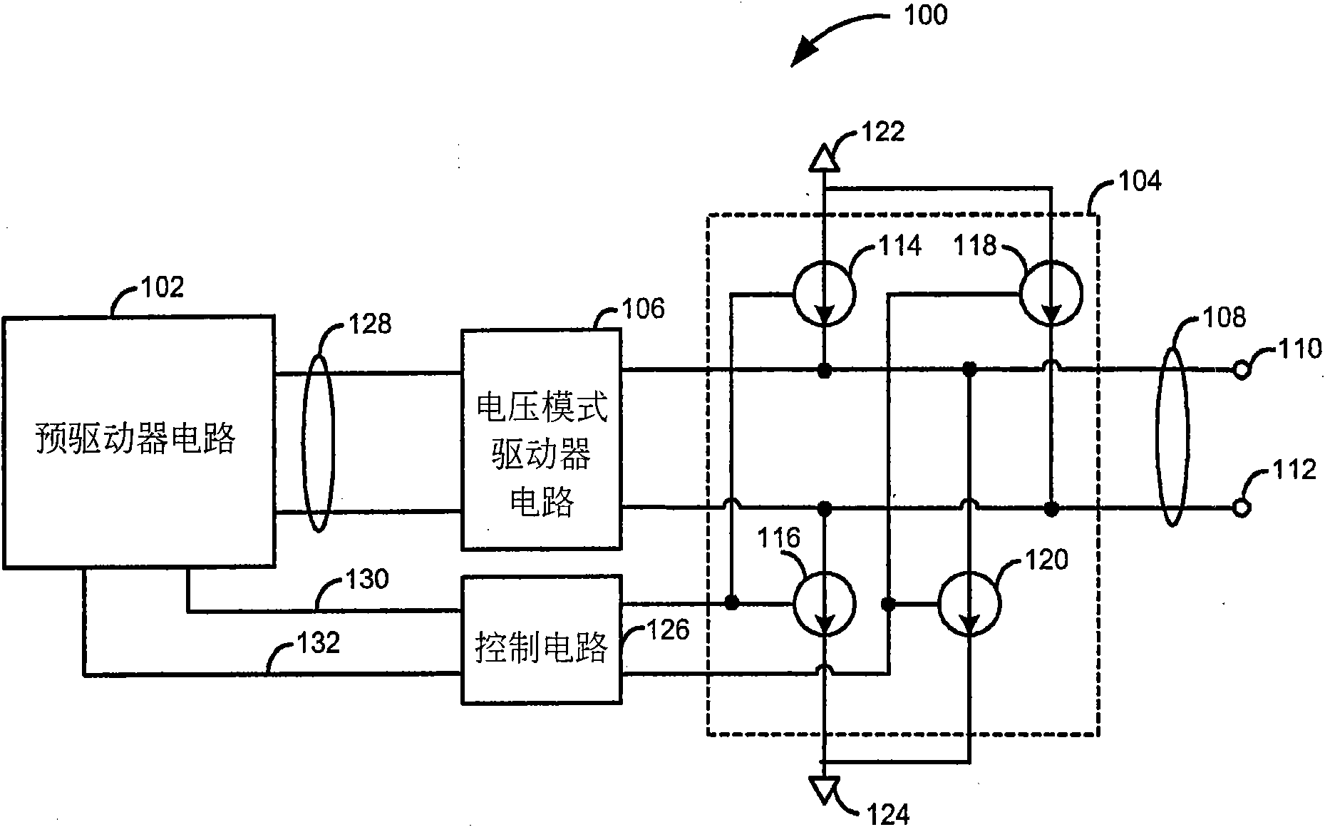
As such, the de-emphasis circuit 104 consumes more power when using the extra 9mA to de-emphasize the differential voltage transmission signal 108

Method used


Image

  • De-emphasis circuit for a voltage mode driver used to communicate via a differential communication link
  • De-emphasis circuit for a voltage mode driver used to communicate via a differential communication link
  • De-emphasis circuit for a voltage mode driver used to communicate via a differential communication link

Examples


Embodiment Construction

[0064] As used herein, the term "circuitry" may include electronic circuitry, one or more processors (e.g., shared, dedicated, or group processors such as, but not limited to, microprocessors, DSPs, or central processing unit), memory executing one or more software or firmware programs, combinational logic circuits, ASICs, and / or other suitable components that provide the described functionality. Furthermore, those of ordinary skill in the art will appreciate that the operation, design, and organization of a "circuit" can be described by a hardware description language (e.g., Verilog TM , VHDL, or other suitable hardware description language) to describe.

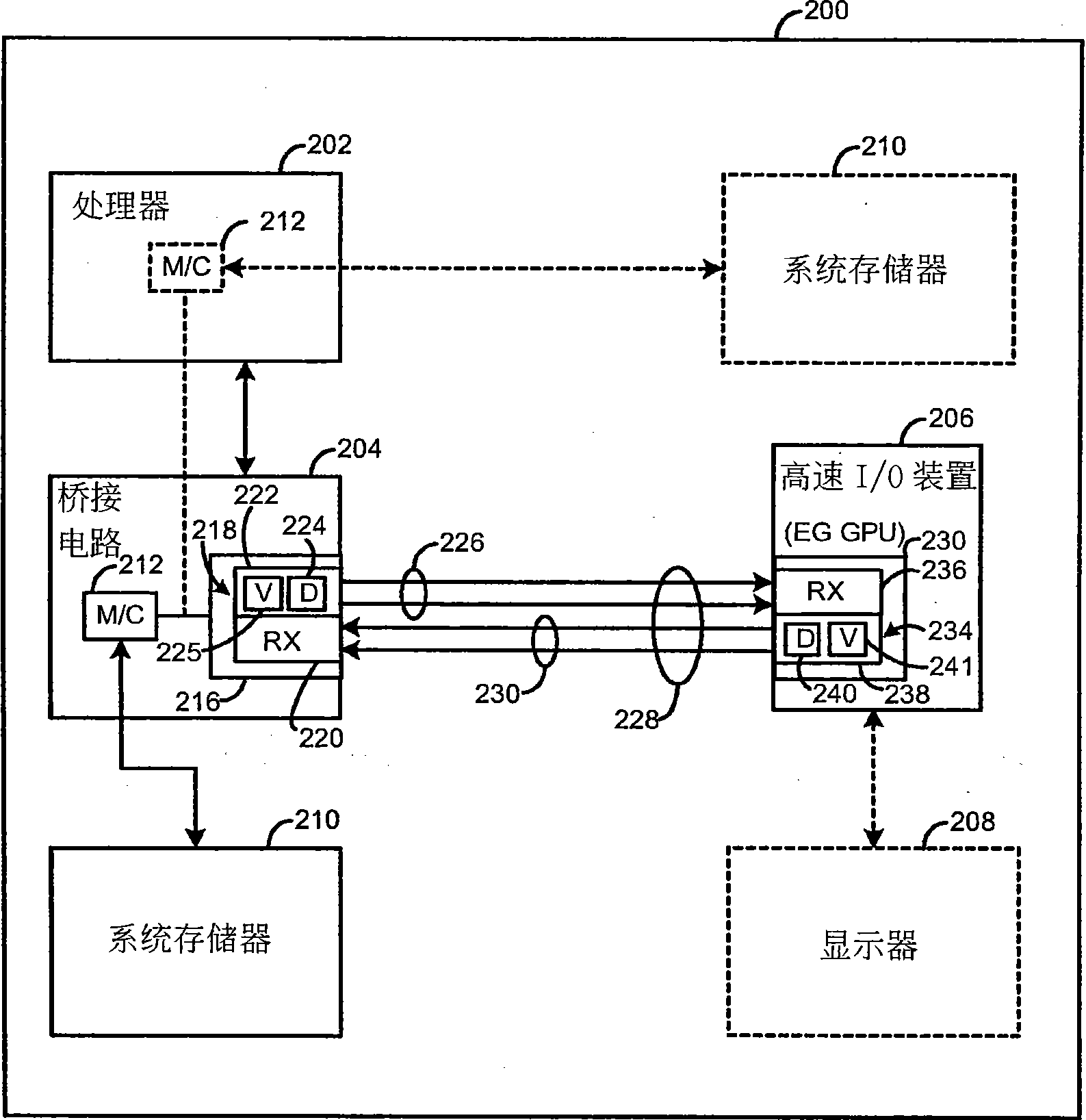
[0065] Referring to FIG. 2, a device 200 (e.g., wireless telephone, mobile and / or stationary computer, printer, LAN interface (wireless and / or wired), media player, video decoder and / or encoder) is depicted. , and / or any other suitable digital device) example functional block diagrams. The device 200 includes at least one...


PUM


Abstract

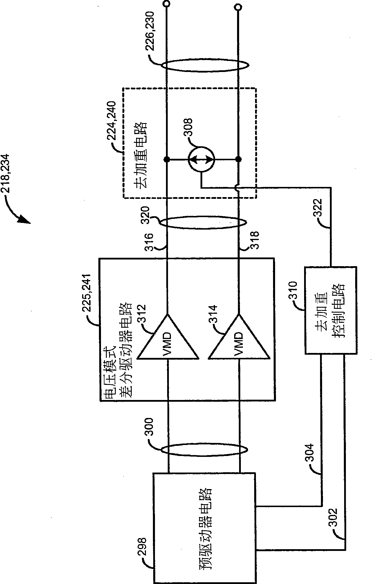
A circuit for de-emphasizing information transmitted via a differential communication link (226) includes a voltage mode differential circuit (225) and a bi-directional current source circuit (308). The voltage mode differential circuit (225) includes a first and second output terminal (316, 318). The voltage mode differential circuit (225) provides a first voltage via the first output terminal (316) and second voltage via the second output terminal (318) in response to a differential input voltage. The bi-directional current source circuit (308) is operatively coupled between the first and second terminals. The bi-directional current source circuit (308) selectively provides current in a first and second direction between the first and second terminals based on the first and second voltage.

Description

technical field [0001] The present invention relates to a voltage-mode driver de-emphasis circuit that communicates via a differential communication link, in particular, to a voltage-mode driver de-emphasis circuit that reduces power consumption. Background technique [0002] Increases in processing speed of devices (eg, graphics processors, hard disks, network cards, and other high-speed I / O devices) have created demands for increased communication bandwidth between devices. One way to increase the bandwidth between the bridge circuit and the I / O device is to use a differential communication link such as PCI Express TM 、HyperTransport TM , SATA, USB, and other suitable differential communication links. This interface is a flexible, hybrid serial-parallel interface format using multiple differential communication links (often called lanes). Each link consists of a transmit runway for transmitting information and a receive runway for receiving information. [0003] In hig...

Claims


Application Information

Patent Timeline
IPC IPC(8): H04L1/18H03K17/693H04L25/02H04L1/08
CPCH03K19/0019H04L25/0272H04L25/0286H04L1/08
Inventor Y·梁A·鲍姆迪卡M·许M-J·李
Owner ADVANCED MICRO DEVICES INC
Learn More