Method for recycling waste silicon powder in production process of trichlorosilane

A production process, trichlorosilane technology, applied in separation methods, chemical instruments and methods, silicon, etc., can solve the problems affecting the health of workers in the factory environment, waste silicon powder discharge and stacking are easy to catch fire, and there is no water spray in the leaching tower. and other problems, to achieve the effect of promoting rapid development, remarkable energy saving effect, and eliminating safety accidents

Inactive Publication Date: 2012-03-14
河南尚宇新能源股份有限公司
View PDF5 Cites 0 Cited by
  • Summary
  • Abstract
  • Description
  • Claims
  • Application Information

AI Technical Summary

Problems solved by technology

This method can ensure the regeneration effect of the dust removal equipment, but because the dust gas contains a small amount of trichlorosilane, and trichlorosilane meets water to form silicon dioxide solids and hydrogen chloride gas
Silica will block the nozzle of the spraying device in the tower, and in severe cases, it will cause no water spraying in the washing tower, and the silicon powder will be discharged directly from the top of the washing tower, causing serious environmental pollution; the generated hydrogen chloride gas dissolves in water to form hydrochloric acid , the spray liquid of the leaching tower is acidic, causing certain corrosion to the circulating water pump, and the generated hydrochloric acid needs to be treated before being discharged, resulting in secondary pollutants
Because the surface of waste silicon powder is stained with a small amount of hydrogen chloride, trichlorosilane and other gases, and trichlorosilane meets the moisture in the air and generates pungent hydrogen chloride gas, which affects the environment of the factory area and the health of employees; Because of the fine particle size, temperature of 100~200℃, and flammable trichlorosilane gas attached to the surface, waste silicon powder is easy to catch fire when it is discharged and stacked, and there are certain safety hazards.

Method used


Image

  • Method for recycling waste silicon powder in production process of trichlorosilane
  • Method for recycling waste silicon powder in production process of trichlorosilane

Examples


Embodiment 1

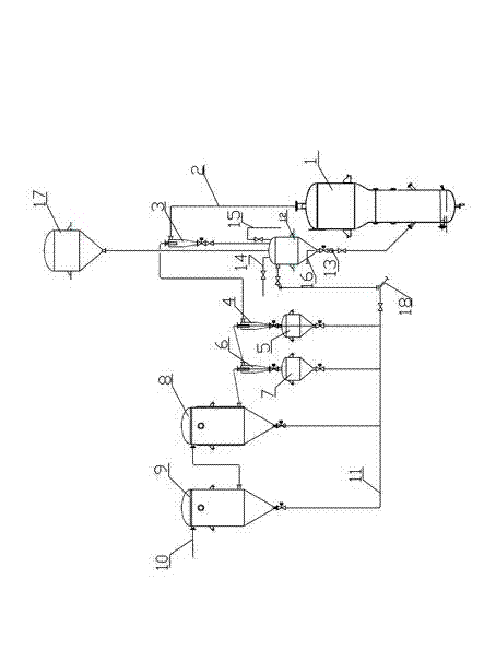
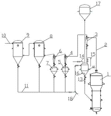
[0022] The mixed gas generated in the synthesis furnace enters the high-efficiency cyclone separator 3 through the mixed gas outlet pipe 2 of the synthesis furnace. The outlet pressure of the high-efficiency cyclone separator 3 is 30-35 Kpa, and the separated silicon powder particles enter the silicon powder recovery tank 12. The gas from the high-efficiency cyclone separator 3 passes through the first-stage cyclone separator 4 and the second-stage cyclone separator 6 in turn. The outlet pressure of the first-stage cyclone separator is 28~33Kpa, and the outlet pressure of the second-stage cyclone separator is 26~30Kpa. . The separated silicon powder particles enter the primary slag storage tank 5 and the secondary slag storage tank 7 respectively, and then enter the silicon powder recovery tank 12 through the slag blowing pipeline 11; the mixed gas from the secondary cyclone separator 6 passes through the primary The bag filter 8 and the secondary bag filter 9, the outlet pres...

Embodiment 2

[0033] The mixed gas generated in the synthesis furnace enters the high-efficiency cyclone separator 3 through the mixed gas outlet pipe 2 of the synthesis furnace. The outlet pressure of the high-efficiency cyclone separator 3 is 30Kpa, and the separated silicon powder particles enter the silicon powder recovery tank 12. The gas coming out from the high-efficiency cyclone separator 3 passes through the primary cyclone separator 4 and the secondary cyclone separator 6 successively. The outlet pressure of the primary cyclone separator is 28Kpa, and the outlet pressure of the secondary cyclone separator is 26Kpa. The separated silicon powder particles enter the primary slag storage tank 5 and the secondary slag storage tank 7 respectively, and then enter the silicon powder recovery tank 12 through the slag blowing pipeline 11; the mixed gas from the secondary cyclone separator 6 passes through the primary Bag filter 8 and secondary bag filter 9, the outlet pressure of the first b...

Embodiment 3

[0036]The mixed gas generated in the synthesis furnace enters the high-efficiency cyclone separator 3 through the mixed gas outlet pipe 2 of the synthesis furnace. The outlet pressure of the high-efficiency cyclone separator 3 is 35 Kpa, and the separated silicon powder particles enter the silicon powder recovery tank 12. The gas from the high-efficiency cyclone separator 3 passes through the first-stage cyclone separator 4 and the second-stage cyclone separator 6 successively. The outlet pressure of the first-stage cyclone separator is 33Kpa, and the outlet pressure of the second-stage cyclone separator is 30Kpa. The separated silicon powder particles enter the primary slag storage tank 5 and the secondary slag storage tank 7 respectively, and then enter the silicon powder recovery tank 12 through the slag blowing pipeline 11; the mixed gas from the secondary cyclone separator 6 passes through the primary Bag filter 8 and secondary bag filter 9, the outlet pressure of the firs...


PUM


Abstract

The invention discloses an equipment for producing trichlorosilane by comprehensively utilizing waste silicon powder. The equipment comprises a trichlorosilane synthetic furnace mixed gas outlet pipe connected with a high-efficiency cyclone separator; wherein a material discharge port of the high-efficiency cyclone separator is connected with a silicon powder recovery tank; a gas outlet of the high-efficiency cyclone separator is connected with a primary cyclone separator; a primary slag storage tank is arranged below the primary cyclone separator; the gas outlet of the primary cyclone separator is connected with a secondary cyclone separator; a secondary slag storage tank is arranged below the secondary cyclone separator; the gas outlet of the secondary cyclone separator is connected with a primary bag-type dust remover and a secondary bag-type dust remover in turn; both the material discharge ports of the primary bag-type dust remover and the secondary bag-type dust remover are connected with the silicon powder recovery tank through slag blowing pipes; and the material discharge port of the silicon powder recovery tank is connected with a recovery port of the trichlorosilane synthetic furnace. The equipment has the characteristics of obvious energy conservation effect, high environmental protection benefit, high safety factor, unique process, simplicity and long service life, and is easy to operate and the like.

Description

technical field [0001] The invention belongs to the technical field of trichlorosilane production, and in particular relates to a method for recycling waste silicon powder in the trichlorosilane production process. Background technique [0002] Judging from the development of my country's trichlorosilane industry, most enterprises have not installed waste silicon powder recovery devices. In most enterprises, the waste silicon powder generated after the mixed gas dedusting is directly discharged to the leaching tower, and a few manufacturers use the waste silicon powder to be discharged into a large-capacity ash storage tank, and then manually discharged regularly. [0003] The first method is equivalent to the wet dust removal method. The circulating water pump pumps the water into the leaching tower in multiple layers, and the gas containing silicon powder enters from the middle and lower part of the tower, and is absorbed by the liquid sprayed from the multi-layer spraying...

Claims


Application Information

Patent Timeline
Patent Type & Authority Patents(China)
IPC IPC(8): C01B33/107C01B33/02B01D50/00
CPCY02P20/10
Inventor 张世斌秦永红王良珣王市民张丽娜
Owner 河南尚宇新能源股份有限公司
Why Eureka
Try Eureka