Method for improving magnetic property of oriented silicon steel through laser scribing

A technology of oriented silicon steel and laser scoring, which is applied in the directions of laser welding equipment, inorganic material magnetism, furnace type, etc., can solve the problems of large plate shape damage, frequent maintenance, and reduced magnetic induction of oriented silicon steel sheets, so as to improve the quality and grade , Overcoming frequent maintenance and no deterioration of magnetic induction

Active Publication Date: 2011-02-23
武汉钢铁有限公司
View PDF6 Cites 41 Cited by
  • Summary
  • Abstract
  • Description
  • Claims
  • Application Information

AI Technical Summary

Problems solved by technology

[0004] For the above-mentioned mechanical indentation method, the high hardness of the grain-oriented silicon steel sheet will cause the gear rollers to wear out after a short period of use, requiring frequent maintenance
For the above chemical etching method, it is necessary to apply a mask before etching, and remove the mask after etching. The process is more complicated than the mechanical indentation method, and the magnetic induction of the grain-oriented silicon steel sheet is seriously reduced.
For the above Q-switched carbon dioxide laser irradiation method and the method of forming a molten resolidified layer on the surface of the grain-oriented silicon steel sheet, although there are no problems of frequent maintenance and complicated processes in the first two methods, the heat input of the Q-switche

Method used


Image

  • Method for improving magnetic property of oriented silicon steel through laser scribing
  • Method for improving magnetic property of oriented silicon steel through laser scribing
  • Method for improving magnetic property of oriented silicon steel through laser scribing

Examples


Example Embodiment

[0024] The method for improving the magnetic properties of grain-oriented silicon steel by laser marking of the present invention will be described in further detail below in conjunction with the accompanying drawings and specific examples:

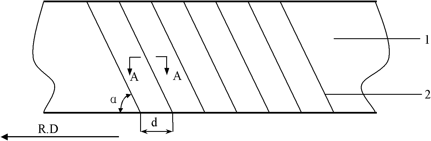
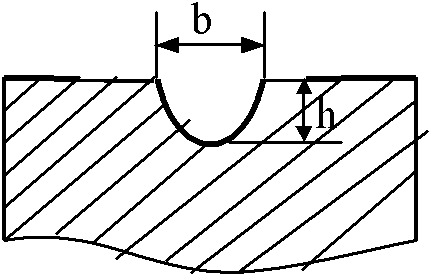
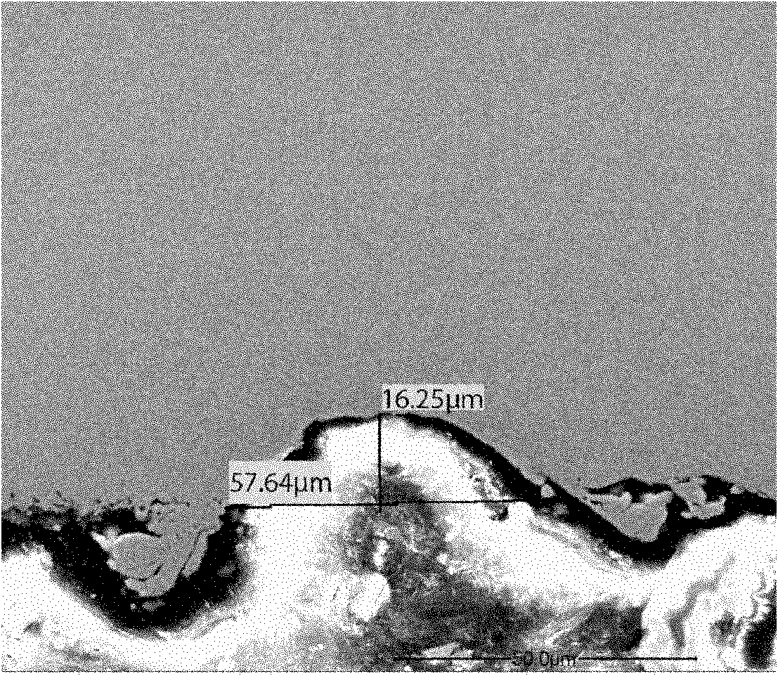
[0025] As shown in Figures 1 and 2, linear or dotted grooves 2 are engraved on the surface of the high magnetic induction oriented silicon steel sheet 1, and each linear or dotted groove 2 is aligned with the rolling direction of the oriented silicon steel sheet 1 (Fig. The included angle α=78~88° in the R.D direction) shown in , the distance between adjacent linear or dotted linear grooves 2 along the rolling direction of grain-oriented silicon steel sheet 1 is d=3~5mm, each line or dot The groove depth h of the linear groove 2 is 15 to 30 μm, and the groove width b is 50 to 65 μm. It is obtained by the following method: adjusting the working parameters of the laser beam produced by the fiber laser to the following range: spot diameter D...


PUM


Abstract

The invention discloses a method for improving the magnetic property of oriented silicon steel through laser scribing. In the method, a plurality of parallel line-shaped or dotted line-shaped grooves are scribed on the surface of an oriented silicon steel sheet subjected to high temperature annealing by adopting laser beam, the inclined angle alpha between each line-shaped or dotted line-shaped groove and the rolling direction of the oriented silicon steel sheet is 78 to 88 DEG, the distance d of adjacent line-shaped or dotted line-shaped grooves along the rolling direction of the oriented silicon steel sheet is 3 to 5 mm, the groove depth h is 15 to 30 mu m, and the groove width b is 50 to 65 mu m. The preferable working parameters of the laser beam are that: the diameter D of a light spot is 7 to 13 mu m, and the peak power density N of an irradiation point is 108 to 109 W/cm<2>. By adopting laser scribing, the plate type of the oriented silicon steel sheet is not damaged and iron loss also can be remarkably reduced, the iron loss reduction effect of the laser scribing cannot disappear after stress relieving annealing at the temperature of 800 DEG C for 2 hours, the lamination factor cannot be reduced, and the magnetic induction basically does not worsen. Meanwhile, the process of the method is simple, the production is easy to control, and the method is particularly suitable for improving the performance of the high-magnetic induction oriented silicon steel sheet, and the oriented silicon steel sheet can be used for a wound iron core transformer and also can be used for a laminated iron core transformer after being treated.

Description

technical field [0001] The invention relates to the manufacturing technology of grain-oriented silicon steel, in particular to a method for improving the magnetic properties of grain-oriented silicon steel by laser scoring. Background technique [0002] Oriented silicon steel sheets are mainly used as core materials for transformers. Reducing the iron loss of grain-oriented silicon steel sheet can reduce the energy loss in the working process of the transformer, which is very important for energy saving and emission reduction. The iron loss of grain-oriented silicon steel sheets consists of hysteresis loss and eddy current loss, and the eddy current loss is further divided into classical eddy current loss and abnormal eddy current loss. The abnormal eddy current loss is the eddy current loss based on the movement of the magnetic domain wall, which is proportional to the moving speed of the magnetic domain wall. At the same frequency, the moving speed of the magnetic domain ...

Claims


Application Information

Patent Timeline
IPC IPC(8): H01F1/16C21D8/12B23K26/06C21D9/46
CPCC21D9/46C21D8/12C21D8/1277
Inventor 朱业超王向欣毛炯辉王若平胡守天张福斌林勇杨皓
Owner 武汉钢铁有限公司
Why Eureka
Try Eureka