
Laser grooving and scribing system and laser grooving and scribing method for solar panel

A solar cell panel and laser scribing technology, which is applied in laser welding equipment, welding equipment, metal processing equipment, etc., can solve problems such as damage and lower photoelectric conversion efficiency of solar cells, so as to improve the accuracy of scribing lines, reduce processing costs, The effect of increasing the preheating temperature

Inactive Publication Date: 2014-08-06
江苏迈健生物科技发展股份有限公司
View PDF5 Cites 0 Cited by
  • Summary
  • Abstract
  • Description
  • Claims
  • Application Information

AI Technical Summary

Problems solved by technology

However, the ultrafast short-wavelength laser will also generate a large stress between the processed microscopic area and the adjacent unprocessed area, thereby causing unnecessary damage to the adjacent unprocessed area, including fine thermal damage, thermal stress and mechanical stress. damage, they can directly or indirectly reduce the final photoelectric conversion efficiency of solar cells

Method used


Image

  • Laser grooving and scribing system and laser grooving and scribing method for solar panel
  • Laser grooving and scribing system and laser grooving and scribing method for solar panel
  • Laser grooving and scribing system and laser grooving and scribing method for solar panel

Examples


Embodiment 1

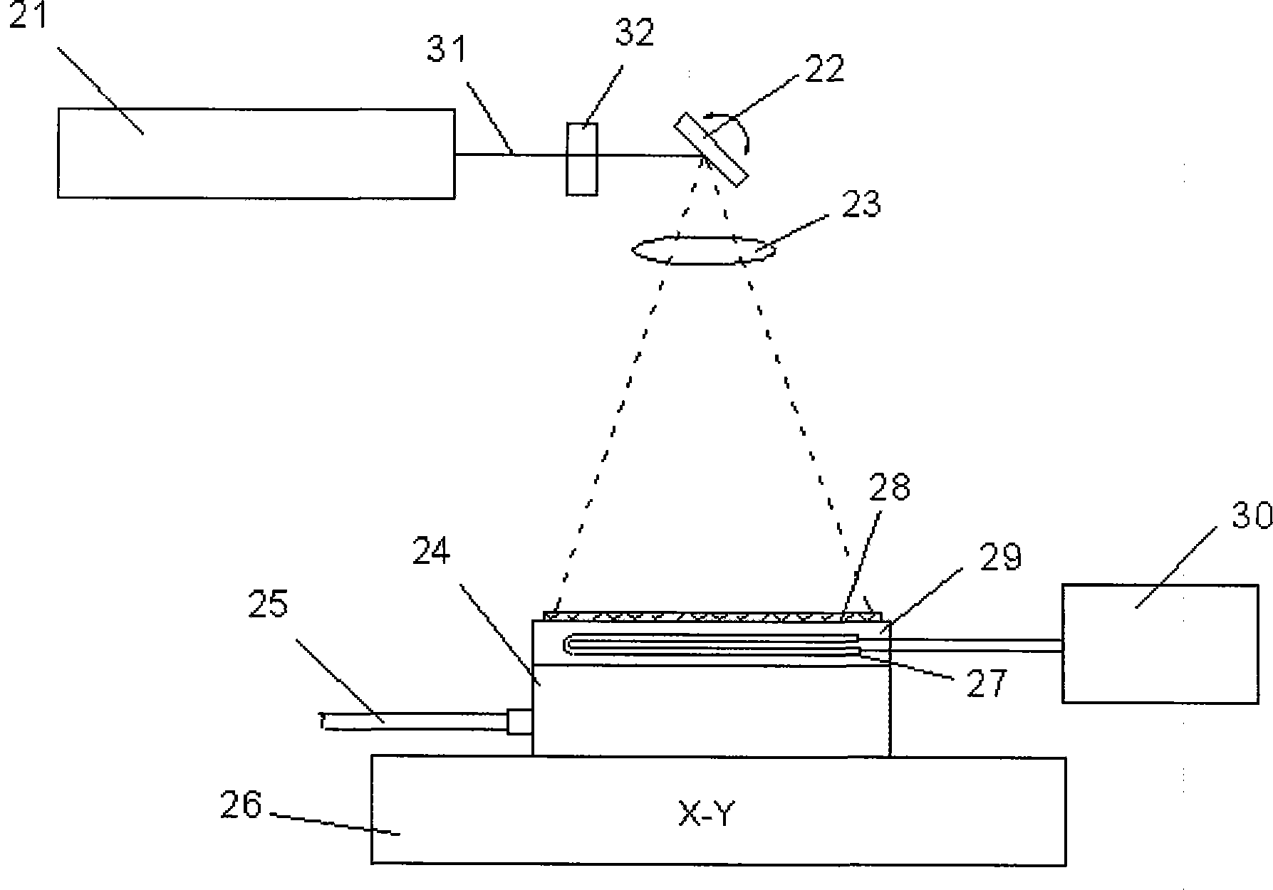
[0028] Such as figure 2 Shown: the present invention comprises laser 21, laser scanner 22, lens 23, stage 24, vacuum tube 25, mobile platform 26, electric heater 27, battery plate 28, heating device 29, temperature controller 30, laser beam 31 And the beam spreading device 32.

[0029] Such as figure 2 As shown: the laser 21 is used to generate a laser light source, and the output end of the laser 21 generates a laser beam 31, and the laser beam 31 enters the laser scanner 22 after passing through the beam diffusion device 32; the laser scanner 22 is located at the beam diffusion The device 32 corresponds to the other side connected to the laser 21 . The laser scanner 22 scans the battery board 28 on the stage 24 according to the set pattern, so as to obtain the set shape on the battery board 28 . A stage 24 is provided below the laser scanner 22, and a lens 23 is arranged between the stage 24 and the laser scanner 22, and the lens 23 is used to keep the focus of the lase...

Embodiment 2

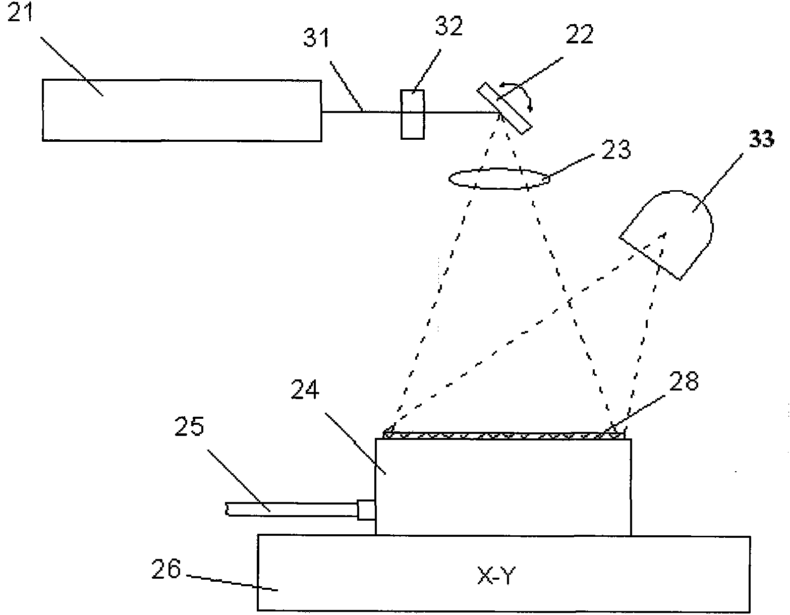
[0041] Such as image 3 Shown: the present invention includes a laser 21, a laser scanner 22, a lens 23, an object stage 24, a vacuum tube 25, a moving stage 26, a battery board 28, a laser beam 31, a beam diffusing device 32 and an infrared heater 33.

[0042] Such as image 3 As shown: the laser beam 31 generated by the laser 21 is input to the laser scanner 22 through the beam spreading device 32 , and the lens 23 and the stage 24 are arranged below the laser scanner 22 . The stage 24 is provided with a number of positioning holes and positioning grooves, and the positioning holes and positioning grooves are all connected with the vacuum tube 25 on the stage 24 . Correspondingly, the other end of the stage 24 adjacent to the laser 22 is provided with a fixedly connected mobile platform 26 . An infrared heater 33 is arranged above the stage 24, and the infrared heater 33 is a quartz lamp tube or a ceramic heater. The battery board 28 is placed on the end of the stage 24 c...


PUM


Abstract

The invention relates to a laser grooving and scribing system for a solar panel, which comprises a laser, wherein a light beam spreading device is arranged on an output light path of the laser, a laser scanner is arranged on the light beam spreading device by corresponding to the other side connected with the laser, and an object stage is arranged below the laser scanner; and the heating device is arranged on the object stage. The panel is placed on the object stage by corresponding to the end part located by the heating device, the object stage is heated through an electric heater, and the panel is placed on the object stage after heating for heating the panel to a certain temperature; or the surface of the panel is heated through an infrared heater, thereby improving the pre-heating temperature of the panel, reducing the power requirement of the laser, improving the processing speed of the laser, reducing the processing cost and improving the scribing precision; and the laser grooving and scribing system can reduce the damages of laser to a non-processed region which is adjacent to a scribed region during the precision scribing process of the panel, and the damages include very fine heat damages, heat stress damages and mechanical stress damages.

Description

technical field [0001] The invention relates to a laser scribing system and a scribing method, in particular to a solar panel laser scribing system and a scribing method, belonging to the technical field of laser precision machining. Background technique [0002] Photovoltaic technology, a technology that directly converts solar energy into electricity, is expanding at an unprecedented rate around the world, driven by various factors, such as energy prices and climate warming. Many countries have formulated very strict standards for the production and use of renewable energy, stipulating the increasing proportion of renewable energy in public electricity consumption. The cost of solar cell power generation is also steadily decreasing, making it gradually become an alternative product that is comparable to or even cheaper than conventional power generation. [0003] At present, silicon wafer solar cells account for more than 85% of the photovoltaic market. It is the most mat...

Claims


Application Information

Patent Timeline
Patent Type & Authority Patents(China)
IPC IPC(8): B23K26/362B23K26/70
Inventor 陈力吴周令
Owner 江苏迈健生物科技发展股份有限公司
Learn More