Electrolytic equipment for sewage treatment by EFT
A technology of electrolysis equipment and complete sets of equipment, applied in water/sewage treatment, water/sludge/sewage treatment, chemical instruments and methods, etc., can solve problems such as short service life, easy aging, and easy fouling
- Summary
- Abstract
- Description
- Claims
- Application Information
AI Technical Summary
Problems solved by technology
Method used
Image
Examples
Embodiment 1
[0104] Example 1. EFT sewage treatment equipment one
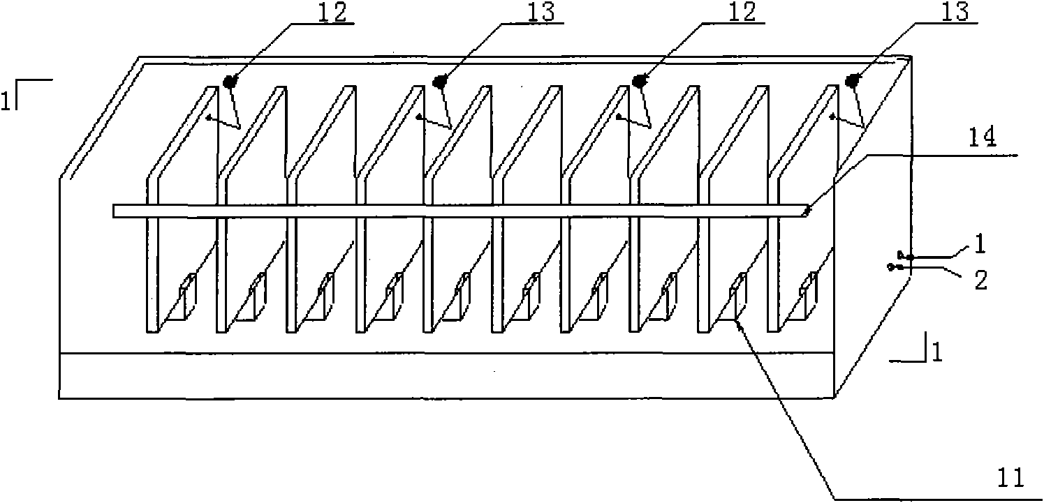
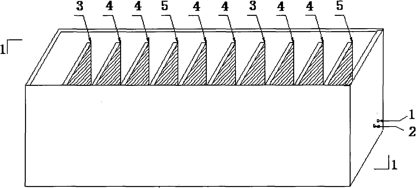
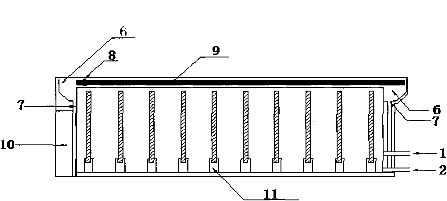
[0105] As shown in the drawings, the interior of the sewage treatment equipment of the present invention consists of an anode plate, two transition plates, a cathode plate, and two transition plates alternately arranged in sequence, totaling 31 plates.
[0106] The anode plate is composed of 7 layers of graphite layer, glass fiber reinforced plastic layer, graphite layer, aluminum layer, graphite layer, glass fiber reinforced plastic layer, graphite layer; wherein the thickness of each graphite layer is 0.5 mm or more; the thickness of aluminum layer is 1 mm or more; The thickness of the layer is 0.5 mm or more, and the preparation process is the same as the process of the transition plate of the present invention. After being flattened by glue bonding, the anode plate is obtained.
[0107] The cathode plate is composed of 7 layers of graphite layer, active metal layer after sprinting, graphite layer, glass fiber reinforced plast...
Embodiment 2
[0109] Example 2. EFT sewage treatment equipment two
[0110] As shown in the drawings, the interior of the sewage treatment equipment of the present invention consists of an anode plate, two transition plates, a cathode plate, and two transition plates alternately arranged in sequence, totaling 31 plates.
[0111] The anode plate is composed of 7 layers of graphite layer, glass fiber reinforced plastic layer, graphite layer, aluminum plate layer, graphite layer, glass fiber reinforced plastic layer, graphite layer; wherein the thickness of each graphite layer is 0.8mm; the thickness of the aluminum plate layer is more than 1mm; the glass fiber reinforced plastic layer The thickness is 0.8mm, and the preparation process is the same as that of the transition plate of the present invention. After being flattened by glue bonding, the anode plate is obtained.
[0112] The cathode plate is composed of a 5-layer structure consisting of a graphite layer, an aluminum plate layer, a graphite ...
Embodiment 3
[0114] Example 3. EFT sewage treatment equipment three
[0115] As shown in the drawings, the interior of the sewage treatment equipment of the present invention consists of an anode plate, two transition plates, a cathode plate, and two transition plates alternately arranged in sequence, totaling 31 plates.
[0116] The anode plate is composed of 7 layers of graphite layer, glass fiber reinforced plastic layer, graphite layer, aluminum layer, graphite layer, glass fiber reinforced plastic layer, graphite layer; wherein the thickness of each graphite layer is 0.6mm; the thickness of aluminum layer is 1.2mm; the glass fiber reinforced plastic layer The thickness is 0.8mm, and the preparation process is the same as that of the transition plate of the present invention. After being flattened by glue bonding, the anode plate is obtained.
[0117] The cathode plate is composed of a three-layer structure consisting of a graphite layer, an aluminum layer, and a graphite layer in sequence; w...
PUM
| Property | Measurement | Unit |
|---|---|---|
| Thickness | aaaaa | aaaaa |
| Thickness | aaaaa | aaaaa |
| Thickness | aaaaa | aaaaa |
Abstract
Description
Claims
Application Information
 - R&D
- Intellectual Property
- Life Sciences
- Materials
- Tech Scout
- Unparalleled Data Quality
- Higher Quality Content
- 60% Fewer Hallucinations
Browse by: Latest US Patents, China's latest patents, Technical Efficacy Thesaurus, Application Domain, Technology Topic, Popular Technical Reports.
© 2025 PatSnap. All rights reserved.Legal|Privacy policy|Modern Slavery Act Transparency Statement|Sitemap|About US| Contact US: help@patsnap.com


