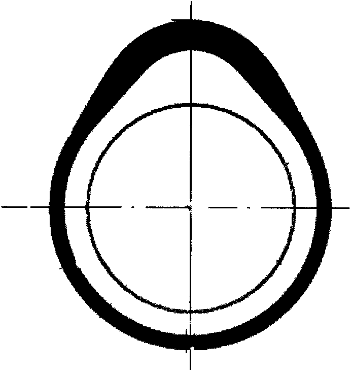
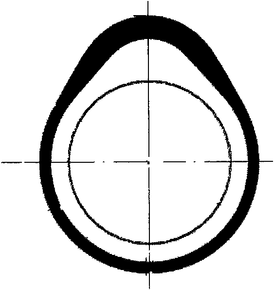
Manufacturing method of cam of engine camshaft
A manufacturing method and camshaft technology, which are applied in the direction of manufacturing tools, furnace types, furnaces, etc., to achieve the effects of reducing production costs, improving production efficiency, and high precision
- Summary
- Abstract
- Description
- Claims
- Application Information
AI Technical Summary
Problems solved by technology
Method used
Image
Examples
Embodiment 1
[0035] ① Prepare the raw material, that is, the mixed powder of iron alloy and carbon. The ratio is: iron alloy (1.5% chromium, 0.2% molybdenum, 98.3% iron) is 99.45%, carbon is 0.25%, and then added content is 0.3% Organosilane wax lubricants;
[0036] ② Press the above mixed powder on a press with a pressure greater than 600Mpa to make the density greater than 7.45g / cm 3 Cam parts; pressing can adopt warm pressing forming, mold heating forming;
[0037] ③ Sintering, the cam part is sintered at a temperature of 1250° C., and the sintering time is 20 minutes. The sintering is carried out in a vacuum sintering furnace or in a sintering furnace based on nitrogen and the proportion of hydrogen is 10vol%;
[0038] ④Heat treatment: Determine the heat treatment process according to the chemical composition requirements of the sintered parts. The carbon potential of heat treatment is 0.8%, the quenching temperature is 840°C, and the heat preservation is 30 minutes. The tempering tem...
Embodiment 2
[0042] ① Prepare the raw material, that is, the mixed powder of iron alloy and carbon. The ratio is: iron alloy (1.5% chromium, 0.2% molybdenum, 98.3% iron) is 99.1%, carbon is 0.60%, and then added content is 0.3% Organosilane wax lubricants;
[0043] ② Press the above mixed powder on a press with a pressure greater than 600Mpa to make the density greater than 7.40g / cm 3 The cam parts; pressing can adopt warm pressing forming, mold heating forming.
[0044] ③Sintering, the cam part is sintered at a temperature of 1250°C, the sintering time is 30 minutes, and the sintering is carried out in a vacuum sintering furnace or in a sintering furnace based on nitrogen and the proportion of hydrogen is 10vol%;
[0045] ④Heat treatment, using high-frequency heat treatment, the depth of the heat treatment hardened layer is 2.5mm at the tip of the cam and the transition part, and 1.8mm at other parts, the hardness HV1 is greater than 520, the tempering temperature is 200 ° C, and the hea...
Embodiment 3
[0048]① Prepare the raw materials, that is, the mixed powder of iron, chromium, carbon and nickel. The ratio is: iron alloy (1.5% chromium, 0.2% molybdenum, 98.3% iron) is 97.95%, carbon is 0.25%, nickel is 1.5%, and then add 0.3% organosilane wax lubricant;
[0049] ② Press the above mixed powder on a press with a pressure greater than 600Mpa to make the density greater than 7.4g / cm 3 The cam parts; pressing can adopt warm pressing forming, mold heating forming.
[0050] ③Sintering, the cam part is sintered at a temperature of 1300°C, the sintering time is 30 minutes, and the sintering is carried out in a vacuum sintering furnace or in a sintering furnace based on nitrogen and the proportion of hydrogen is 75vol%;
[0051] ④Heat treatment: Determine the heat treatment process according to the chemical composition requirements of the sintered parts. The heat treatment quenching temperature is 900°C, the heat treatment carbon potential is 0.8%, the heat preservation is 35 minu...
PUM
| Property | Measurement | Unit |
|---|---|---|
| Tensile strength | aaaaa | aaaaa |
| Yield strength | aaaaa | aaaaa |
| Impact strength | aaaaa | aaaaa |
Abstract
Description
Claims
Application Information
 - R&D
- Intellectual Property
- Life Sciences
- Materials
- Tech Scout
- Unparalleled Data Quality
- Higher Quality Content
- 60% Fewer Hallucinations
Browse by: Latest US Patents, China's latest patents, Technical Efficacy Thesaurus, Application Domain, Technology Topic, Popular Technical Reports.
© 2025 PatSnap. All rights reserved.Legal|Privacy policy|Modern Slavery Act Transparency Statement|Sitemap|About US| Contact US: help@patsnap.com


