Manufacturing method of powder metallurgy cam

A powder metallurgy and cam technology, which is applied in the field of iron-based powder metallurgy cam preparation, can solve the problems of parts failure, sintered cam cam competition on the engine, time-consuming and labor-intensive problems, increase the extrusion process, realize surface densification, reduce The effect of production costs

Active Publication Date: 2015-11-04
NBTM NEW MATERIALS GRP
View PDF5 Cites 12 Cited by
  • Summary
  • Abstract
  • Description
  • Claims
  • Application Information

AI Technical Summary

Problems solved by technology

Traditional camshafts and camshafts are produced by integral casting, which is difficult to meet the above requirements at the same time, and there are generally the following defects: 1. The use of materials is not reasonable; 2. It is difficult to produce dense cams in the traditional integral casting or forging production mode Arranged compact structure; 3. The traditional method of manufacturing camshafts requires a large number of machining processes and consumes a lot of machining man-hours. It is difficult to make new breakthroughs in machine tools, tools, fixtures, operators and operating areas; 4. Traditional processing requires The wear resistance strengthening treatment of the cam surface (such as chilling, quenching or remelting of the cast camshaft, carburizing and quenching of the surface of the forged camshaft, etc.) is carried out on the integral camshaft, accompanied by deformation, most of which are artificial Straightening is time-consuming and labor-intensive, and it is difficult to ensure accuracy; 5. The machining of the cam profile is difficult, and it is also an important factor affecting the quality of processing
It has a wide range of applications in many fields, but it is still difficult to compete with cams of other processes on the engine.
This is mainly because there are pores on the surface of the powder metallurgy cam, and the existence of pores will reduce the contact fatigue strength of the cam surface and cause part failure

Method used


Image

  • Manufacturing method of powder metallurgy cam
  • Manufacturing method of powder metallurgy cam
  • Manufacturing method of powder metallurgy cam

Examples


Embodiment 1

[0042] ① Prepare the raw materials, that is, the mixed powder of iron, chromium, molybdenum and carbon. The ratio is: iron alloy (chromium is 3.0%, molybdenum is 0.5%, other unavoidable substances, less than 1%, iron is the balance) is 98.8% ; Carbon is 0.70%, and then add lubricant with a content of 0.5%;

[0043] ②Compress the above mixed powder under a pressure of 600MPa to a density of 6.95g / cm 3 The cam blank;

[0044] ③Sintering, the cam part is sintered at a temperature of 1200°C, the sintering time is 20 minutes, and the sintering is carried out in a vacuum sintering furnace;

[0045] ④Annealing: the annealing temperature is 850°C; the atmosphere is nitrogen, the annealing holding time is 60 minutes, and the cooling rate from the annealing temperature to 300°C after annealing is 0.1°C / S;

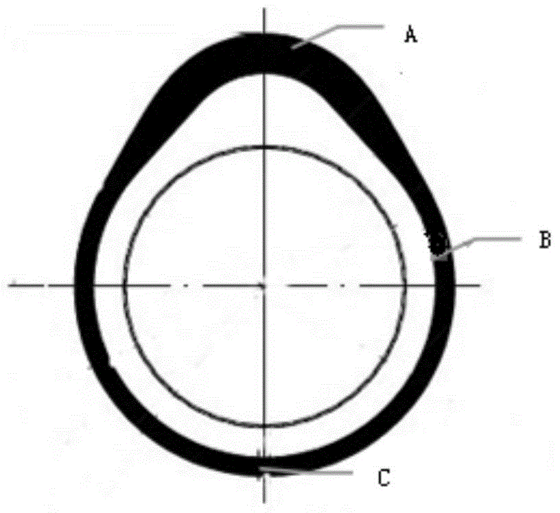
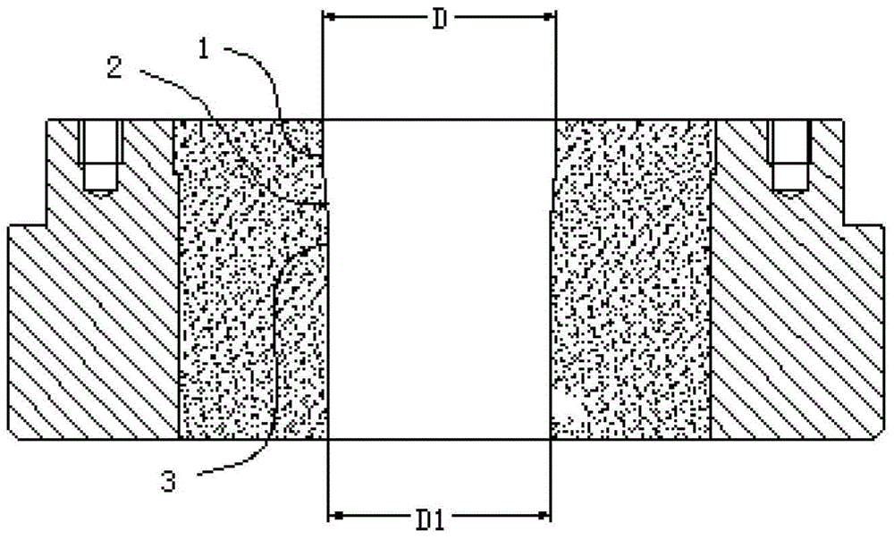
[0046] ⑤ Extrusion (finishing): Extrusion is carried out on a press modified by an extrusion molding machine or a finishing press, and the extrusion deformation is greater than 5% ...

Embodiment 2

[0049] ① Prepare the raw materials, that is, the mixed powder of iron, chromium, molybdenum and carbon. The ratio is: iron alloy powder (chromium is 3.0%, molybdenum is 0.5%, other unavoidable substances, less than 1%, iron is the balance) is 50 %, pure iron powder is 48.5%; carbon is 1.0%, and then add lubricant with a content of 0.5%;

[0050] ②Compress the above mixed powder under a pressure of 600MPa to a density of 7.2g / cm 3 cam blank.

[0051] ③Sintering, the cam part is sintered at a temperature of 1120°C, the sintering time is 20 minutes, and the sintering is carried out in a sintering furnace based on nitrogen and the proportion of hydrogen is 10vol%;

[0052] ④Annealing: The annealing temperature is 850°C; the atmosphere is nitrogen, the annealing holding time is 60 minutes, and the cooling rate from the annealing temperature to 300°C after annealing is 0.1°C / S.

[0053] ⑤ Extrusion (finishing): Extrusion is performed on a press modified by an extrusion molding mac...

Embodiment 3

[0058] ① Prepare the raw materials, that is, the mixed powder of iron, chromium, molybdenum and carbon. The ratio is: iron alloy powder (chromium is 1.7%, molybdenum is 0.3%, other unavoidable substances, less than 1%, iron is the balance) is 99.1 %; carbon is 0.4%, and then add a lubricant with a content of 0.5%;

[0059] ② Warm press the above mixed powder under a pressure of 600MPa to a density of 6.60g / cm 3 The cam blank;

[0060] ③Sintering, the cam part is sintered at a temperature of 1200°C, the sintering time is 60 minutes, the sintering is carried out in a vacuum sintering furnace, and annealed at 890°C for 60 minutes during the cooling stage after sintering, after annealing, from the annealing temperature to The cooling rate between 300°C is 0.15°C / S;

[0061] ④Extrusion (finishing): Extrusion is carried out on a press modified by an extrusion molding machine or a finishing press, and the extrusion deformation is greater than 8% in the diameter direction, that is, ...


PUM

PropertyMeasurementUnit
densityaaaaaaaaaa
densityaaaaaaaaaa
densityaaaaaaaaaa

Abstract

A manufacturing method of a powder metallurgy cam is disclosed. Material composition contains, by weight, 0.2-1.5% of carbon, 0-4% of copper, 0-2% of nickel, 0-11% of molybdenum, 0-18% of chromium, 0-12% of tungsten, 0-10% of vanadium, no more than 2% of unavoidable impurities and the rest of iron. The preparation method comprises the following steps: mixing the above raw materials to obtain a mixed powder, and adding 0.1-1 wt% of a lubricant; compacting the mixture into a cam green body with its density being 6.25-7.4 g/cm<3>; sintering the cam green body at 1000-1350 DEG C for 5-180 min; annealing the cam green body in a nonoxidizing atmosphere at the annealing temperature of 750-1080 DEG C and keeping warm for 5-200 min; extruding through an extrusion moulding machine or a press converted from a finishing press with the extrusion deformation degree being greater than 2% in the diameter direction; and carrying out heat treatment and processing so as to obtain a finished product. The manufacturing process is simple. The prepared cam has high precision and good surface finish. By the manufacturing method, production cost is reduced and production efficiency is enhanced. In comparison with a traditional powder metallurgy process, the manufacturing process of the invention has advantages as follows: density of the product is higher, and surface densification is basically realized.

Description

technical field [0001] The invention belongs to the field of powder metallurgy, in particular to a method for preparing an iron-based powder metallurgy cam. Background technique [0002] The camshaft is an important part of the engine valve train, which is responsible for the timing opening and closing of the intake and exhaust valves of each cylinder of the engine. The camshaft realizes the switch of the valve by the intake and exhaust valves of the cylinder jacked by the cam. [0003] The side of the cam is peach-shaped, and the purpose of its design is to ensure sufficient intake and exhaust of the cylinder, specifically to complete the opening and closing of the valve in the shortest possible time. In addition, considering the durability of the engine and the smoothness of operation, the valve cannot produce too much impact due to the acceleration and deceleration process in the switching action, otherwise it will cause serious wear of the valve, increased noise or othe...

Claims


Application Information

Patent Timeline
Patent Type & Authority Applications(China)
IPC IPC(8): C22C33/02C21D8/00B22F5/08
Inventor 包崇玺毛增光詹学救蔡立山
Owner NBTM NEW MATERIALS GRP
Why Eureka
Try Eureka