Ultra-low temperature circulation refrigeration method employing injectors

A refrigeration method and ejector technology, applied in refrigerators, refrigeration components, refrigeration and liquefaction, etc., can solve the problems of low boiling point components condensing into liquids, low boiling point components boiling point limit, evaporation temperature rise, etc., to improve circulation performance, a wide range of applications, and the effect of reducing the compression ratio

Inactive Publication Date: 2011-04-06
HENAN UNIV OF SCI & TECH
View PDF5 Cites 33 Cited by
  • Summary
  • Abstract
  • Description
  • Claims
  • Application Information

AI Technical Summary

Problems solved by technology

However, in order to ensure the higher working pressure required by the working fluid in the ejector, this technology needs to increase the evaporation pressure of the high boiling point working fluid in the evaporative condenser, which will inevitably lead to an increase in its evaporation temperature, and the increase in the evaporation temperature of the high boiling point working fluid will As a result, the boiling point of the low-boiling point component is greatly limited; if the selected low-boiling point component has a low boiling point, the high-boiling point working fluid with a higher evaporation temperature in the condensing evaporator will not be able to condense the low-boiling point component into a liquid , Therefore, the automatic cascade refrigeration cycle with ejector is more suitable for occasions with high refrigeration temperature, and its use is greatly restricted in occasions with low refrigeration temperature

Method used


Image

  • Ultra-low temperature circulation refrigeration method employing injectors
  • Ultra-low temperature circulation refrigeration method employing injectors
  • Ultra-low temperature circulation refrigeration method employing injectors

Examples


Embodiment Construction

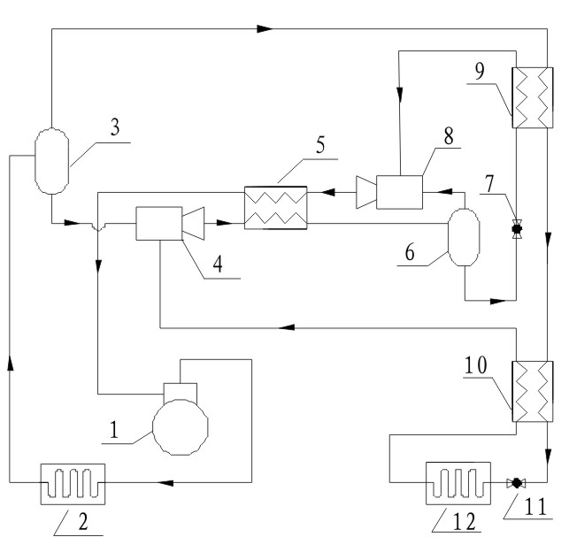
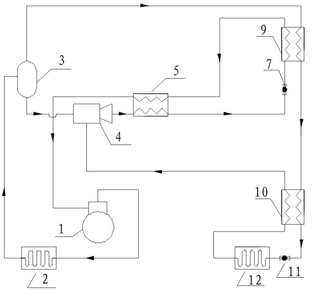
[0025] The refrigerating components involved in the ultra-low temperature cycle refrigeration method with an ejector in the present invention include a compressor 1, a condenser 2, a first gas-liquid separator 3, a first regenerator 5, a first throttling member 7, a condensation evaporation 9, a second regenerator 10, a second throttling element 11 and an evaporator 12, and the refrigeration component also includes a first ejector 4, a second ejector 8 and a second gas-liquid separator 6. Although the method of the present invention involves the above-mentioned refrigeration components common in the refrigeration industry, the connection relationship formed by the above-mentioned refrigeration components and the resulting cycle refrigeration process and effect are different. For this reason, the present invention consists of the above-mentioned refrigeration components and The ultra-low temperature cycle refrigeration process composed of refrigerant is as follows:

[0026] The...


PUM


Abstract

The invention relates to an ultra-low temperature circulation refrigeration method employing injectors. In the method, high-pressure mixed refrigerants compressed by a compressor (1) enter a condenser (2) and then enter a first gas-liquid separator (3) to realize gas and liquid phase separation, liquid refrigerants flowing out of the first gas-liquid separator (3) enter a first injector (4), gas and liquid two-phase mixed work media from an outlet of the first injector (4) are cooled by a first heat regenerator (5) and then enter a second gas-liquid separator (6) to be separated, work fluid of a second injector (8) is processed into low-pressure steam through a first throttling member (7) and a condensing evaporator (9), and the low-pressure steam is pressurized by the second injector (8), flows into the first heat regenerator (5) to be subjected to overheating and then flows back to the compressor (1); and gaseous refrigerants flowing out of the top of the first gas-liquid separator (3) flow into the condensing evaporator (9), are recooled through a second heat regenerator (10) and enter an evaporator (12) through a second throttling member (11) for refrigeration at low temperature, the ultra-low temperature can reach minus 40 DEG C to minus 170 DEG C, and the energy saving effect is good.

Description

technical field [0001] The invention belongs to the technical field of refrigeration, and in particular relates to an ultra-low temperature cycle refrigeration method with an ejector. Background technique [0002] Automatic cascade refrigeration cycle technology is one of the more common technologies in small and medium-sized low-temperature refrigeration equipment. The automatic cascade refrigeration cycle technology was first invented in 1936, and this technology was successfully applied in natural gas liquefaction. At present, the self-cascading refrigeration cycle technology can obtain the low temperature environment from the liquid nitrogen temperature range below 80K to the traditional vapor compression refrigeration temperature range of 230K, and has been continuously promoted in the field of low temperature refrigeration. [0003] The automatic cascade refrigeration cycle technology uses a multi-element zeotropic mixture as the refrigerant. According to the characte...

Claims


Application Information

Patent Timeline
Patent Type & Authority Applications(China)
IPC IPC(8): F25B9/08F25B41/04
Inventor 王林谈莹莹王雨马爱华崔晓龙周西文任秀宏闫晓娜
Owner HENAN UNIV OF SCI & TECH
Why Eureka
Try Eureka