

Process for producing high-quality melamine from urea
A technology of melamine and urea, applied in chemical instruments and methods, reaction of liquid and gas at high temperature, products, etc., can solve problems such as no solution provided
- Summary
- Abstract
- Description
- Claims
- Application Information
AI Technical Summary
Problems solved by technology
Method used
Image

Examples
Embodiment approach 1
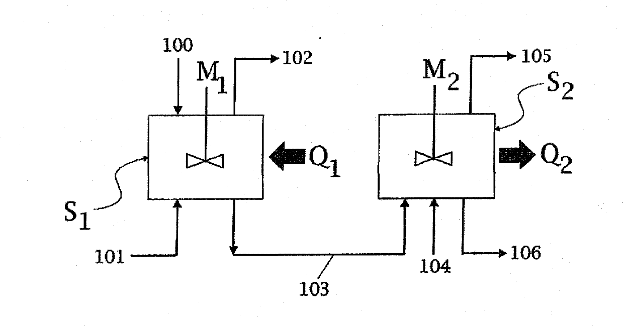
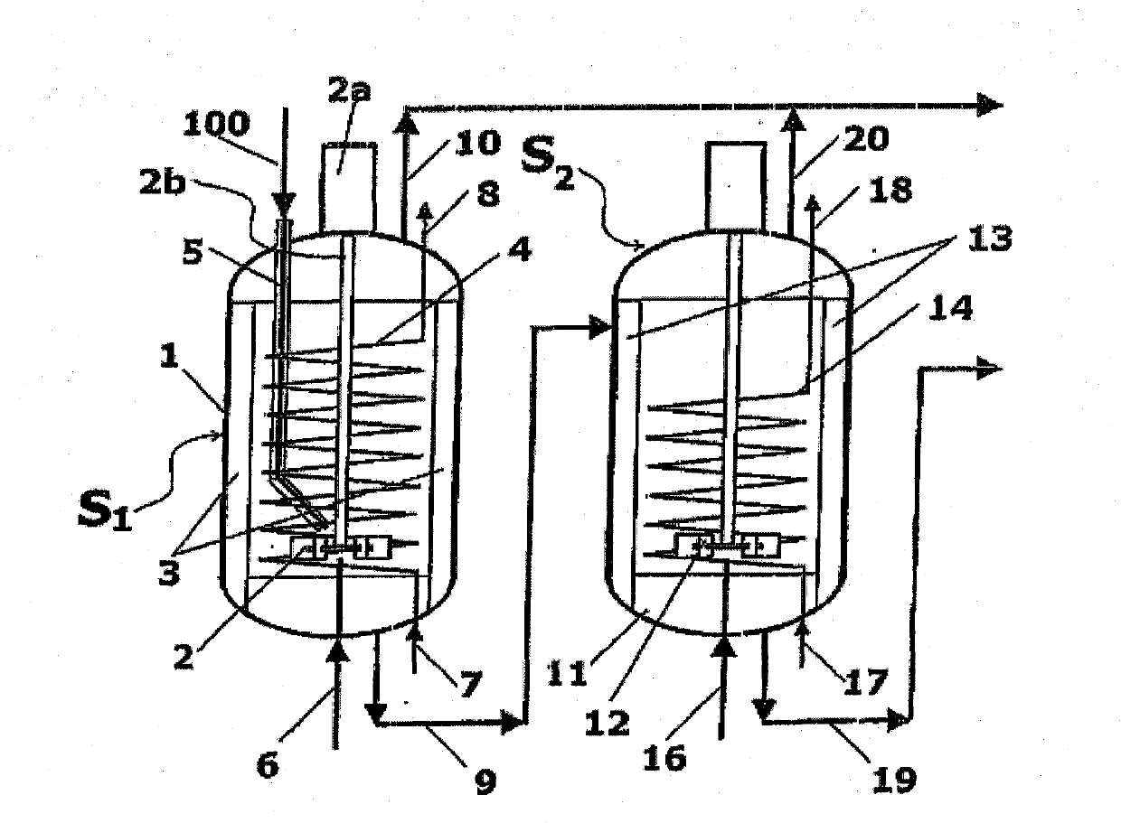
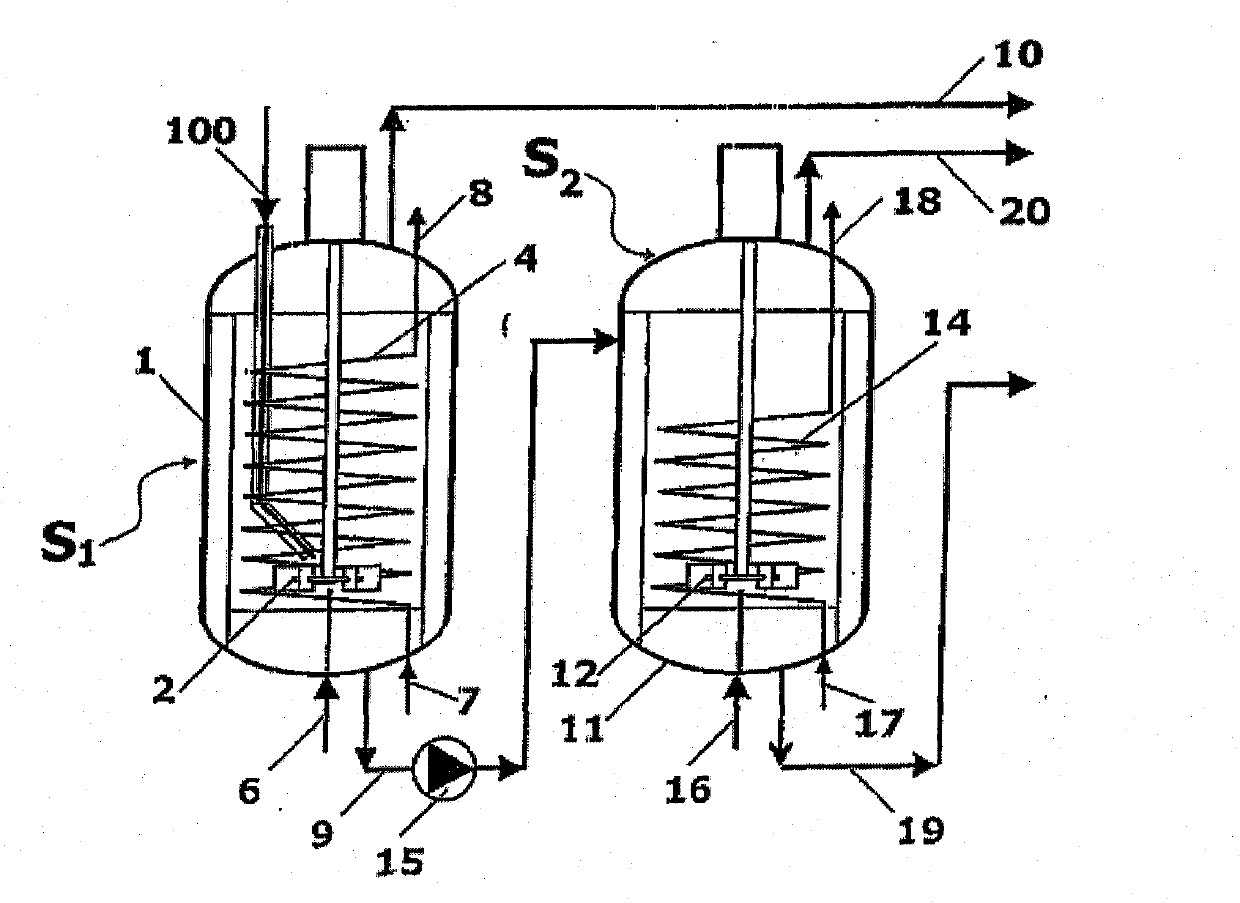
[0064] Such as Figure 2A As shown, the reaction zones S1 and S2 consist of a first stirred vessel 1 and a second stirred vessel 11, which are connected by a line 9 for the melamine melt. The input molten urea 100 enters the first container 1 via the urea line 5 . Further, ammonia ( figure 1 Shown as gas streams 101, 104 in ) are added to the liquid phase in vessels 1 and 11 via lines 6 and 16. Contains mainly ammonia and CO 2 The gaseous products of are collected by lines 10 and 20, respectively. The melamine melt is obtained in line 19 , the outlet of the second vessel 11 .
[0065] Vessel 1 has a mechanical impeller 2 and vertical baffles 3 for continuous stirring of the liquid phase. The impeller 2 has a drive motor 2a and a shaft 2b extending into the container 1 . The baffle 3 satisfies the "full baffle condition", which blocks the tangential entrainment of the liquid, and makes the columnar rotating vortex disappear, and a large amount of energy is transferred to ...
Embodiment approach 2
[0079] In order to reduce equipment and save engineering costs, the method is carried out in a single vessel. Specifically, two reaction stages are carried out in two compartments C1 and C2 of a single horizontal pressure vessel 21 . The two compartments C1 and C2 correspond to the reaction zones S1 and S2; despite having the same cross-section, their volumes can be different due to the different lengths of the horizontal vessels 21 . The two compartments are separated by a baffle 22 which does not completely close the section of the container 21 but leaves a relatively small bottom channel 26 .
[0080] For simplicity, with Figure 2A and 2B Corresponding parts in Embodiment 1 are denoted by the same numerals. Each compartment C1 or C2 has one mechanical stirrer, 2 and 12 respectively. Each compartment also has baffles, 3 and 13 respectively, to satisfy the "full baffle condition" mentioned above. Heat is supplied to the first chamber C1 through the spiral tube 4 , while...
Embodiment approach 3
[0083] In this embodiment, the first and second reaction zones consist of a plurality of stirred reactors distributed in cascades or in series. The advantage is that, for the production capacity of equipment of the same scale, the same reaction can still be completed by reducing the total volume of the liquid. The number of vessels in series making up each stage can conveniently be limited to two or three.
[0084] like Figure 4 As an example, the first stage is constituted by the containers 31A, 31B, and 31C in steps, and the second stage is also formed by the other two containers 32A and 32B in stages. The three vessels 31A to 31C form the first reaction zone S1 and serve as Figure 2A The same role as reactor 1 in the second section; the two reactors in the second section form the second reaction zone S2 and play a role similar to Figure 2A Reactor 11 in the same role. Molten urea is delivered 100 via conduit 33 into the first vessel 31 , while gaseous ammonia is inpu...
PUM
| Property | Measurement | Unit |
|---|---|---|
| purity | aaaaa | aaaaa |
| purity | aaaaa | aaaaa |
| surface area | aaaaa | aaaaa |
Abstract
Description
Claims
Application Information