
Ceramic coating used for heating furnace

A heating furnace and ceramic coating technology, applied in the field of ceramic coating, can solve the problems of low emissivity and short service life, etc.

Inactive Publication Date: 2011-04-20
北京安泰恒业科技有限公司
View PDF4 Cites 29 Cited by
  • Summary
  • Abstract
  • Description
  • Claims
  • Application Information

AI Technical Summary

Problems solved by technology

However, the same type of products still have the disadvantages of low emissivity ε, generally less than 0.9; coating thickness of 1-10mm; short service life of only half a year to one year.

Method used


Image

  • Ceramic coating used for heating furnace
  • Ceramic coating used for heating furnace
  • Ceramic coating used for heating furnace

Examples


Embodiment 1

[0045] Preparation of Ceramic Micropowder:

[0046] Add a certain weight (wt%) in the mixing tank: Fe 2 o 3 60%, ZnO 10%, MnO 2 17%, CrO 3 3%, Ce 2 o 3 3%, CaCO 3 1%, pottery clay 6%, mixed with appropriate amount of water to make a thick paste. Spread the thick slurry evenly on the template, let it dry naturally, and make thin slices. Put the prepared flakes into a calciner, calcinate at 2000°C for 3 hours, and take them out for rapid cooling. Put the calcined tablet into the pulverizer for preliminary pulverization, the particle size is ≤3mm. Put the primary powder material into the fine grinding pulverizer, finely grind and pulverize. Put the finely ground and pulverized materials into the sieving machine for sieving, and the particle size is below 300 mesh as aggregate fine powder, and the rest is returned to the fine grinding operation unit for re-grinding.

Embodiment 2

[0048] Preparation of linear expansion coefficient regulator:

[0049] (1) Preparation of cordierite powder:

[0050] Using orthoethyl silicate (TEOS), aluminum nitrate, and magnesium nitrate as raw materials, according to cordierite (Mg 2 Al 4 Si 5 o 18 ) stoichiometric proportioning, first take a certain stoichiometric amount of aluminum nitrate and magnesium nitrate and dissolve them in an appropriate amount of water, and mix them evenly with a magnetic stirrer. Then weigh a certain amount of ethyl orthosilicate, dissolve it in ethanol solution (the molar ratio of ethyl orthosilicate to ethanol is 1:4), mix well, and configure Si(OC 2 h 5 ) 4 -C 2 h 5 OH solution, under the condition of constant stirring, slowly drop aluminum nitrate and magnesium nitrate aqueous solution to the prepared Si(OC 2 h 5 ) 4 -C 2 h 5 OH solution, stir evenly to obtain a transparent sol, put it in an oven at 60°C for 10 hours to obtain a gel, dry it, and calcinate at a certain temper...

Embodiment 3

[0055] Synthesis of Inorganic Binders

[0056] Put the aluminum sol into the reaction kettle, adjust with aluminum dihydrogen phosphate and sodium silicate to adjust its viscosity and pH, the ratio between the three can be selected arbitrarily according to the needs of viscosity and pH, and mix and stir for 3 hours.


PUM


Abstract

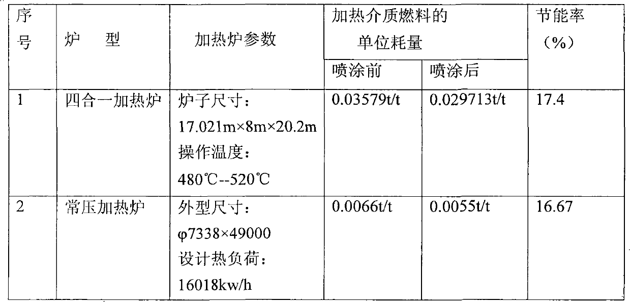
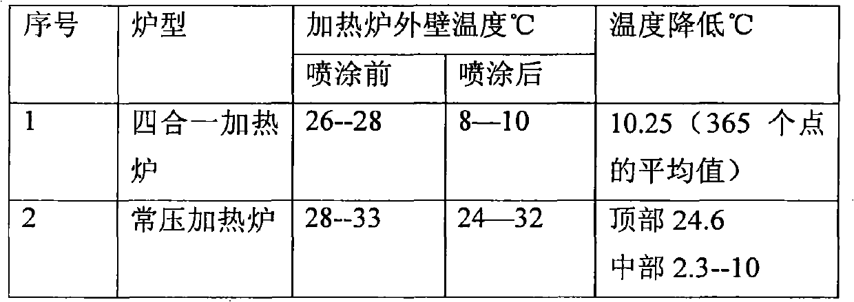
The invention relates to ceramic coating used for a heating furnace. The ceramic coating comprises the following components: ceramic micro powder, an inorganic bonding agent and a linear thermal expansivity regulator. The invention also provides a method for preparing the ceramic coating for the heating furnace. The ceramic coating has the characteristics of having improved radiance and thermal shock resistance, being efficient and energy-saving, prolonging the service life of furnace linings and furnace tubes, improving temperature uniformity and the like, as defined below: (1) the energy consumption is reduced, the energy is saved by more than 3 percent and pollutant discharge is reduced; (2) the temperature uniformity in the heating furnace is improved: (3) the metallurgy stability of the furnace tube of the heating furnace is improved, the coking and scaling of the furnace tub are delayed, and the absorbing capacity of the furnace tube can be maximized; (4) the emissivity of the surface of the refractory lining layer can be maximized so as to increase the secondary radiation of radiant heat (energy) and increase the efficiency of the radiant section; and (5) the outer wall temperature and the exhaust gas temperature of the heating furnace can be reduced by more than 5 percent.

Description

technical field [0001] The invention relates to a ceramic coating, more particularly to a ceramic coating applied on a heating furnace. Background technique [0002] In our country, the development of the national economy has entered a period of high-speed growth, the demand for industrial and civil energy has grown rapidly, and the shortage of energy has begun to restrict the development of the national economy. However, my country's energy utilization rate is only about 30%, and the unit consumption of products is 30-90% higher than that of advanced foreign countries. According to the energy consumption ratio per unit of national output, my country is 3 times higher than the United States and 7 times higher than Japan. Obviously, energy saving and consumption reduction is an important issue to solve the energy shortage in my country's industrial production, especially medium and high temperature heating furnaces and heating equipment are key energy-consuming devices, and t...

Claims


Application Information

Patent Timeline
IPC IPC(8): C04B35/66
Inventor 钱蕾
Owner 北京安泰恒业科技有限公司
Learn More