
Double-shaft MEMS scanning-based heterodyne interference system and method

A technology of heterodyne interference and polarization direction, which is applied in the direction of measuring devices, instruments, and phase-influenced characteristic measurements, and can solve problems such as large vibration errors

Inactive Publication Date: 2011-04-20
THE 3RD ACAD 8358TH RES INST OF CASC +1
View PDF5 Cites 24 Cited by
  • Summary
  • Abstract
  • Description
  • Claims
  • Application Information

AI Technical Summary

Problems solved by technology

[0007] In order to solve the problem that the working wavelength of the existing orthogonal polarization heterodyne interferometer technology is in the visible light band and the vibration error is large, the present invention proposes a dual-axis MEMS scanning heterodyne interferometry system and method

Method used


Image

  • Double-shaft MEMS scanning-based heterodyne interference system and method
  • Double-shaft MEMS scanning-based heterodyne interference system and method
  • Double-shaft MEMS scanning-based heterodyne interference system and method

Examples


specific Embodiment approach 1

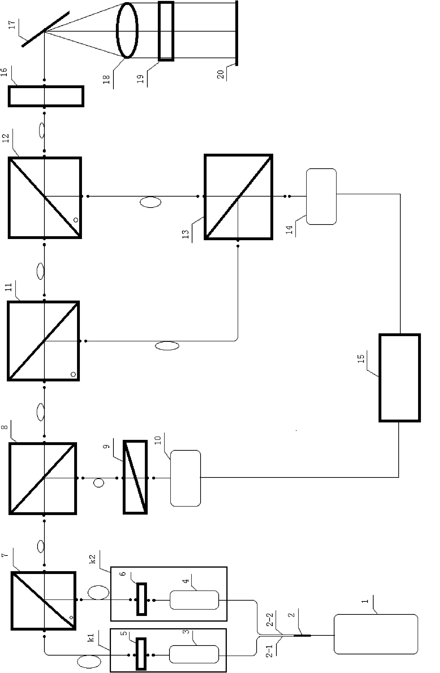
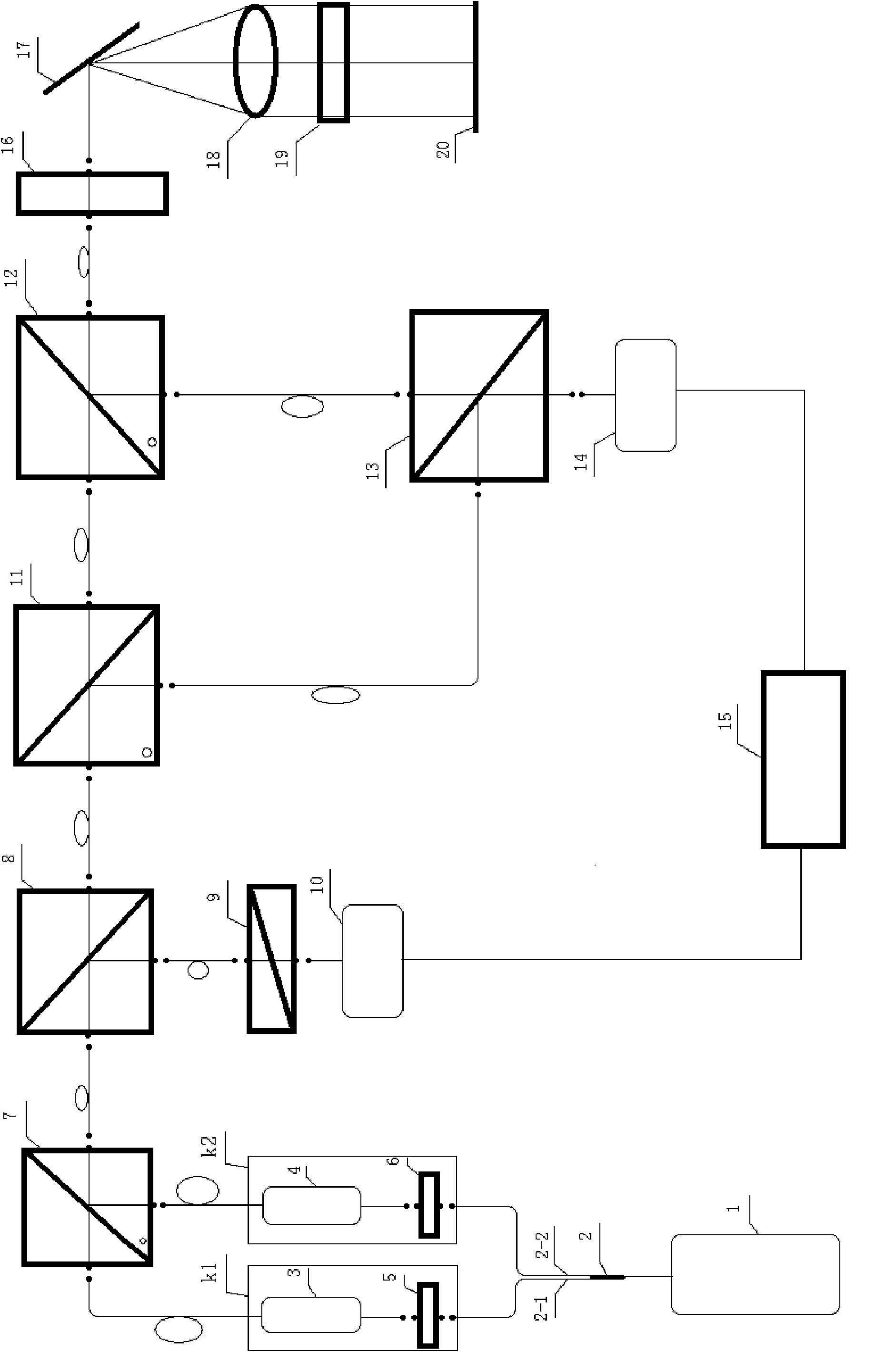
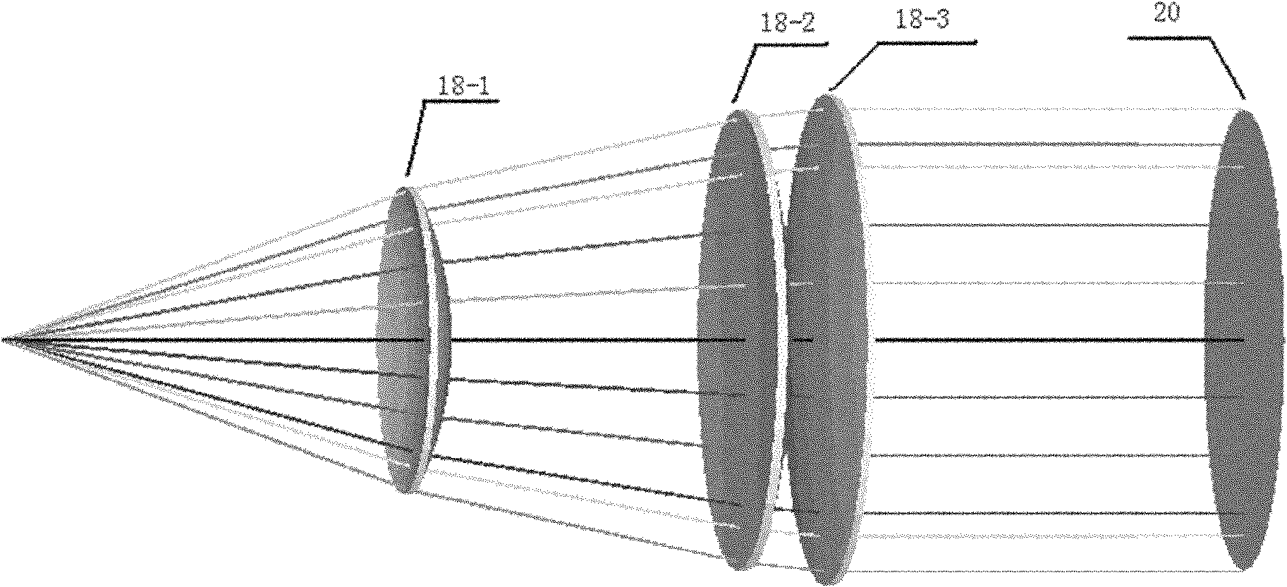
[0012] Specific implementation mode 1. Combination figure 1 with figure 2 Describe this embodiment, the heterodyne interferometry system of biaxial MEMS scanning, it comprises beam splitting prism 8, analyzer 9, first photodetector 10, second polarizing beam splitting prism 11, the 3rd polarizing beam splitting prism 12, Beam combining prism 13, second photodetector 14, computer 15, 1 / 4 wave plate 16, MEMS vibrating mirror 17, F-Theta lens group 18, sample cell 19 to be measured and mirror 20, beam splitting prism 8 will incident The light beam to its central position is split to form a reflected light beam and a transmitted light beam, wherein the reflected light beam is focused on the photosensitive surface of the first photodetector 10 after passing through the analyzer 9, and the signal output terminal of the first photodetector 10 is connected with the computer The first signal input end of 15 is connected, and the light beam transmitted by the second polarizing beam sp...

specific Embodiment approach 2

[0013] Specific embodiment two, combine figure 1 with figure 2 Describe this embodiment mode, this embodiment mode is the further explanation to specific embodiment one, the heterodyne interferometry system of biaxial MEMS scanning, it also comprises orthogonally polarized laser emitting system, and this orthogonally polarized laser emitting system comprises laser 1, optical fiber The beam splitter 2, the first polarization frequency shifting module k1, the second polarization frequency shifting module k2 and the first polarization beam splitting prism 7, the linearly polarized light emitted by the laser 1 enters the fiber beam splitter 2 and is divided into two branches , wherein the light beam of the first branch becomes the first linearly polarized light after passing through the first polarization frequency shifting module k1 and enters the first polarizing beam splitting prism 7, and the first linearly polarized light is transmitted through the first polarizing beam spli...

specific Embodiment approach 3

[0014] Embodiment 3. This embodiment is a further description of Embodiment 2. The laser 1 is a 2 μm laser.

[0015] The working wavelength of the laser 1 is in the 2 μm band which is safe for human eyes.


PUM

PropertyMeasurementUnit
thicknessaaaaaaaaaa
thicknessaaaaaaaaaa

Abstract

The invention discloses a double-shaft micro-electromechanical system (MEMS) scanning-based heterodyne interference system and a double-shaft MEMS scanning-based method, relates to a quick scanning-based laser heterodyne interferometer system and a quick scanning-based laser heterodyne interferometer method, and solves the problems that the operation wavelength of the conventional cross-polarization heterodyne interferometer technology is a visible light wave band and shaking errors are large. The scheme is that: 2 mu m polarization orthogonal laser is subjected to beam splitting by a beam splitter prism to form a transmitted beam and a reflected beam, wherein the reflected beam serving as a reference intermediate frequency signal is transmitted to a computer, S light in the transmission beam is reflected, P light is transmitted, passes through a one fourth wave plate, an MEMS oscillating mirror and an F-theta lens, passes through a to-be-tested sample cell, returns according to the original optical path and is mixed with the P light; and a mixed beam serving as a measurement intermediate frequency signal is sent to the computer, and is processed by the computer so as to obtain the physical quantity information of a to-be-tested sample. The system and the method are suitable for the detection field of infrared optical materials.

Description

technical field [0001] The invention relates to a laser heterodyne interferometer system and method based on fast light scanning. Background technique [0002] Heterodyne interference is to generate a frequency difference between two beams of interfering light waves, so that the original detected information with the optical frequency as the carrier is transferred to the video signal with this frequency difference as the carrier, so that the preamplifier after the photodetector The original DC amplifier can be replaced by an AC amplifier, so that the DC drift of the signal and most of the random noise are effectively suppressed, and the measurement accuracy and repeatability accuracy are improved. Heterodyne interference real-time detection technology is widely used in ultra-smooth surface detection, optical glass surface measurement and film thickness measurement because of its high measurement accuracy, fast measurement speed, high vertical and horizontal resolution. [0...

Claims


Application Information

Patent Timeline
Patent Type & Authority Applications(China)
IPC IPC(8): G01B9/02G01B11/06G01B11/24G01B11/30G01N21/45
Inventor 季一勤王春辉高龙李彦超
Owner THE 3RD ACAD 8358TH RES INST OF CASC
Learn More