Composite unit of automobile exhaust catalytic reduction postprocessor

A post-processor and automobile exhaust technology, applied in chemical instruments and methods, chemical/physical processes, catalyst activation/preparation, etc., can solve problems such as large airflow resistance, limited exhaust pipe diameter, and affecting engine operation, etc., to achieve The effect of simple structure and reliable structure

Inactive Publication Date: 2011-04-27
FAW GROUP
View PDF9 Cites 11 Cited by
  • Summary
  • Abstract
  • Description
  • Claims
  • Application Information

AI Technical Summary

Problems solved by technology

But in fact, after urea is sprayed into the exhaust pipe of the engine through the nozzle, under the high air flow, it cannot be effectively mixed with the exhaust gas until it reaches the catalytic reduction active unit, and the efficiency of its decomposition into NH3 is also low. Poor; or when the high-temperature atmosphere from the engine exhaust manifold reaches the catalytic reduction active end, the temperature drops more, which will also reduce the NOX removal effect
For the thermal insulation problem of catalytic reduction, the foreign method is that the entire system adopts a double-layer metal plate structure, which not only increases the cost of materials, but also makes the packaging process of the assembly extremely complicated
[0006] The patent No. 200720018679.2 of the 'large-displacement engine catalytic reduction post-processing pipeline device' is to install a 'network mixer' on the engine exhaust pipe behind the urea nozzle, the purpose is also to improve the mixing effect, but, The diameter of the exhaust pipe is limited. If the mesh hole is too small, the airflow resistance will be large, which will affect the normal operation of the engine; on the contrary, if the mesh hole is too large, there will be no airflow resistance, but the mixing effect is very poor, and the heat preservation problem is not considered ; The patent No. 200580003880.7 of the 'catalytic reduction muffler' is to add a 'concentric circular porous plate' structure before the entrance of the active end of the catalytic reduction; A 'porous tank-shaped mixing gas chamber is installed upstream of the reducing active end, and the mixed atmosphere flows backwards' to increase the mixing effect. This patent has a problem of complex structure

Method used


Image

  • Composite unit of automobile exhaust catalytic reduction postprocessor
  • Composite unit of automobile exhaust catalytic reduction postprocessor
  • Composite unit of automobile exhaust catalytic reduction postprocessor

Examples


Embodiment Construction

[0015] The present invention will be further described below in conjunction with accompanying drawing:

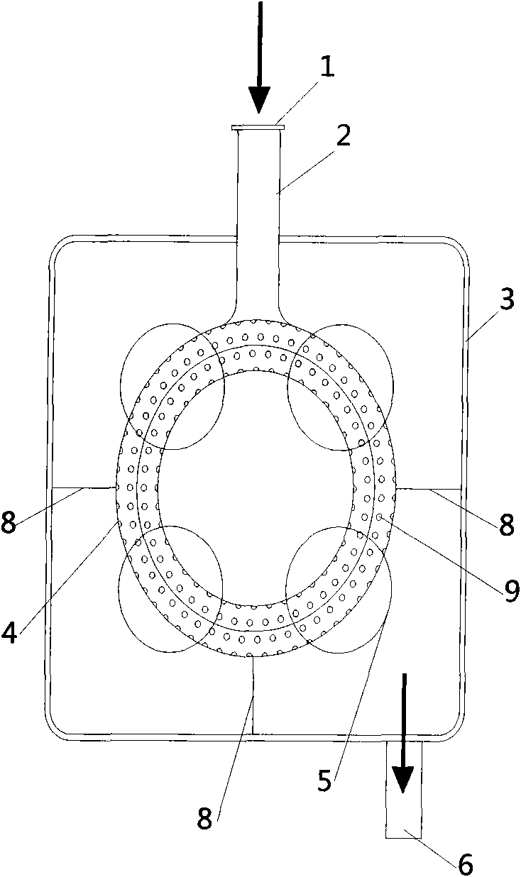
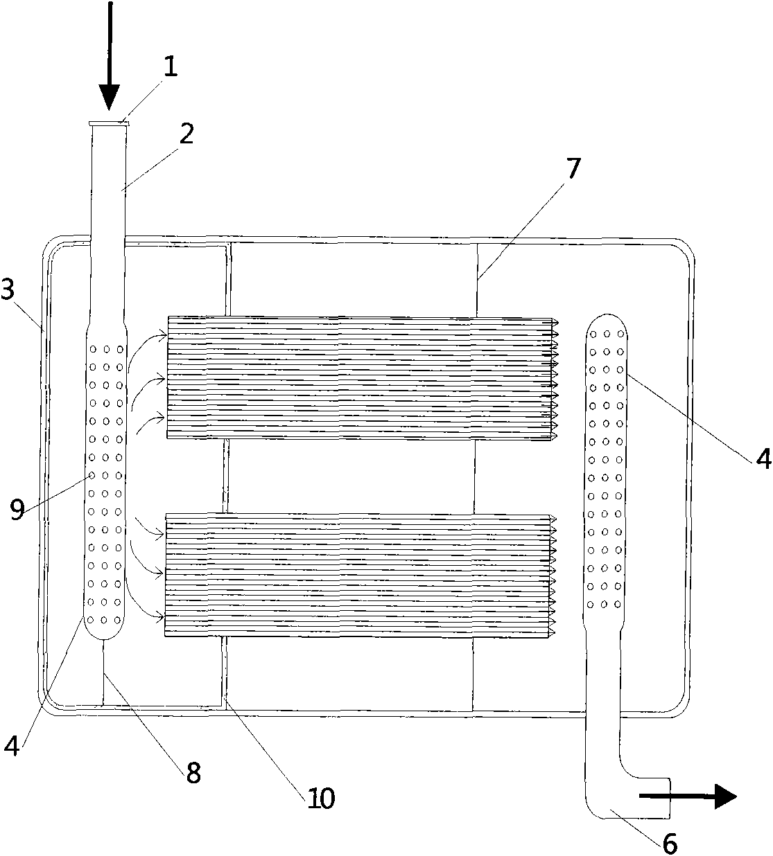
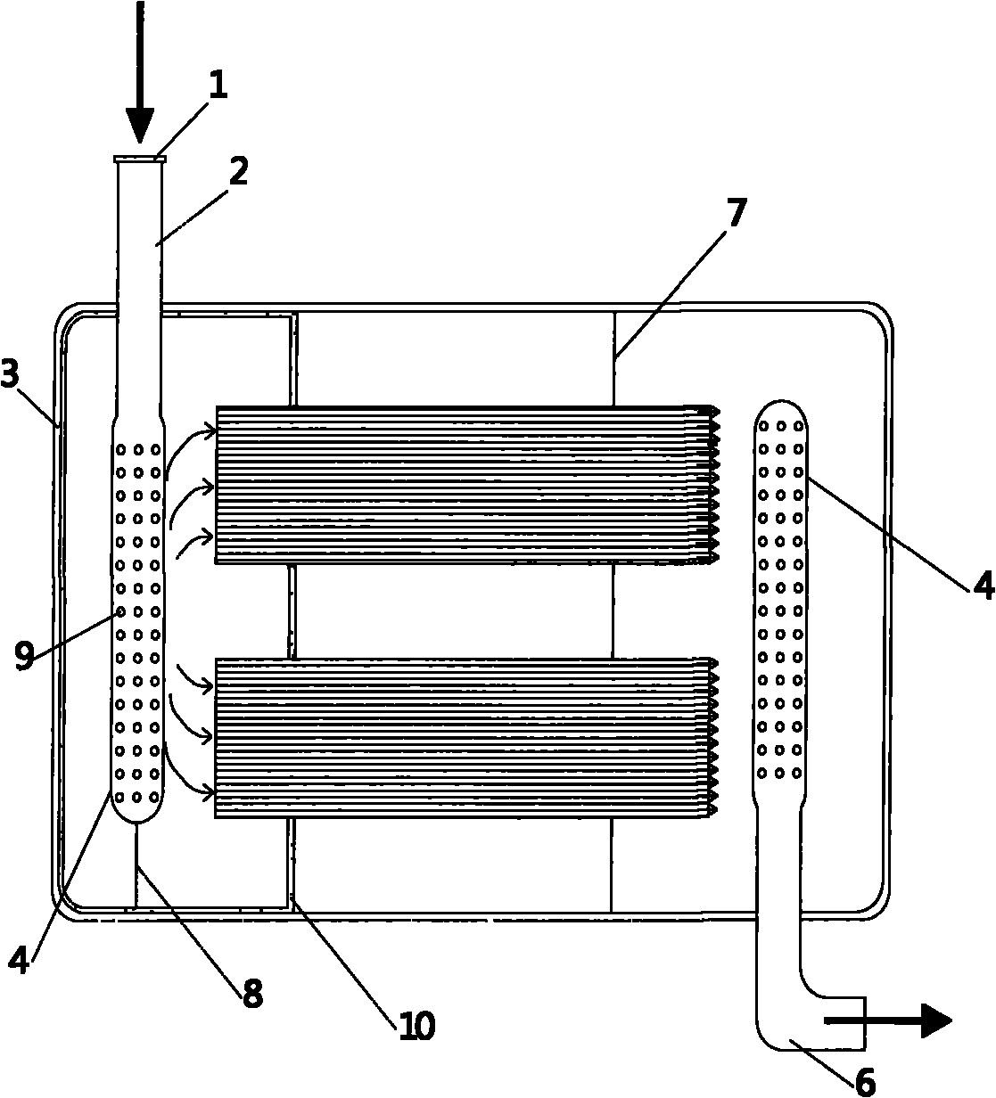
[0016] Such as figure 1 , 2 As shown, a composite unit of an automobile exhaust catalytic reduction post-processor is characterized in that: the composite unit is composed of a connecting flange 1, an intake pipe 2, a housing 3, a mixing unit 4, a catalyst carrier active unit 5, an outlet pipe 6, The supporting partition 7, the reinforcing rib 8, the diversion hole 9 and the ceramic coating 10 are composed; the connecting flange 1 and the intake pipe 2 are argon arc welded, and are welded together with the mixing unit 4 equipped with the diversion hole 9, and the mixing unit 4 is supported by reinforcing ribs 8 and shell 3 welded; catalyst carrier active unit 5 is supported by support partition 7 and shell 3 welded; outlet pipe 6 is welded on shell 3; coating on the inner and outer walls of mixing unit 4 There is a ceramic coating, and the surface layer is uniformly and d...


PUM


Abstract

The invention relates to a composite unit of an automobile exhaust catalytic reduction postprocessor. The composite unit is characterized in that: ceramic coatings are coated on the inner wall and the outer wall of the composite unit, and nano-scale TiO2 granules are uniformly and densely distributed on the surface layer of the composite unit; and the catalytic reduction postprocessor is a square box, ceramic coatings are coated on the inner sides of a cavity partition plate and an end plugging plate of the catalytic reduction postprocessor, and nano-scale TiO2 granules are uniformly and densely distributed on the surface layer of the catalytic reduction postprocessor. The structure of the catalytic reduction postprocessor applied on a commercial automobile, the structural parameters are optimized, the effect of the urea mixing unit is improved, the ceramic coatings are increased, and the nano-scale TiO2 granule uniformly and densely distributed on the surface layer strengthen the urea decomposition function and have de-noising effect, certain heat insulation effect and high practical value.

Description

Technical field: [0001] The invention relates to a composite unit of a catalytic reduction post-processor of automobile exhaust, which is applied to the post-treatment industry of automobile tail gas, and is suitable for a post-processing structure of catalytic reduction and a POC post-processing structure. Background technique: [0002] The current automotive after-treatment technologies include SCR (Selective Catalytic Reduction) catalytic conversion reduction technology, DPF (Diesel Particulate Filter) particle trap, DOC (Diesel Oxidation Catalyst) oxidation catalyst, etc. The essence of catalytic reduction technology is to use urea to decompose NH at high temperature 3 , NH as reducing agent 3 and NO in engine exhaust x The reaction is carried out under the combined action of catalyst and temperature, and under ideal conditions, non-toxic N 2 and H 2 O, so as to achieve the purpose of purification. Since the 1970s, catalytic reduction technology has been developed a...

Claims


Application Information

Patent Timeline
Patent Type & Authority Applications(China)
IPC IPC(8): F01N3/28F01N7/08B01J37/02B01J23/04B01J21/08B01J21/06B01D53/94
CPCY02A50/20
Inventor 张克金应善强王丹崔龙刘国军
Owner FAW GROUP
Why Eureka
Try Eureka