Photoresist-removing method

An object, plasma technology, applied in the direction of photosensitive material processing, etc., can solve the problems of long time, low-k material protective layer loss, low reaction rate, etc., to achieve the effect of reducing damage

Inactive Publication Date: 2011-04-27
SEMICON MFG INT (SHANGHAI) CORP +1
View PDF0 Cites 7 Cited by
  • Summary
  • Abstract
  • Description
  • Claims
  • Application Information

AI Technical Summary

Problems solved by technology

However, only using a lower glue removal pressure also has disadvantages: First, the pump power of the machine needs to be large enough to withstand such a low pressure, and the gas flow rate needs to be large to quickly reduce the pressure in the reaction chamber to so low; the second is the low pressure O 2 The flow will enhance the directional bombardment of the plasma, which will cause the loss of the protective layer of low-k materials to a certain extent.
The disadvantage of this is that the glue removal rate is slow, the throughput is low, and the production capacity is affected
[0009] In addition, due to the CO 2

Method used


Image

  • Photoresist-removing method
  • Photoresist-removing method
  • Photoresist-removing method

Examples


Embodiment Construction

[0031] The present invention will be further described in detail below in conjunction with the accompanying drawings and specific embodiments.

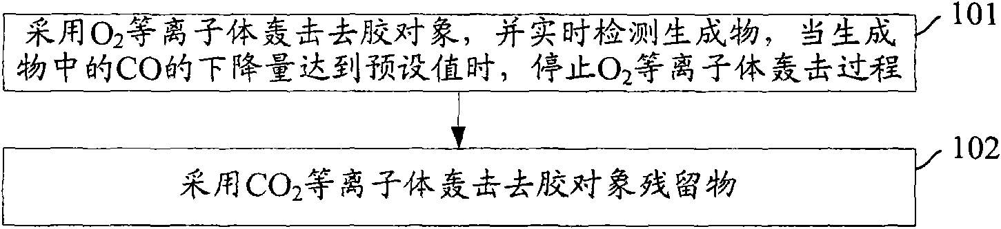
[0032] figure 1 The flow chart of the degumming method provided by the embodiment of the present invention, wherein the degumming object is located above the low-k value interlayer medium, such as figure 1 As shown, the specific steps are as follows:

[0033] Step 101: Adopt O 2 Plasma bombards the object to be glued, and detects the product in real time. When the drop of CO in the product reaches the preset value, stop O 2 Plasma bombardment process.

[0034] The optical emission spectrum can be used to detect the signal value of the product, and the CO signal is sampled according to the preset sampling frequency, for example: 5 times / second. When it is found that the range of the CO signal changes within the first preset time, such as: 3 seconds When it is within the preset range, it is determined that the CO signal is stable, a...


PUM


Abstract

The invention discloses a photoresist-removing method, which comprises the following steps of: bombarding a photoresist-removing object by utilizing an O2 (oxygen) plasma and detecting a CO (carbon monoxide) product; stopping the bombardment of the photoresist-removing object by utilizing the O2 plasma when the decreased amount of CO reaches a preset value; and then bombarding the residue in the photoresist-removing object by utilizing a CO2 (carbon dioxide) plasma. The invention can effectively remove the photoresist of the photoresist-removing object, and can reduce the damage to low-k mediums.

Description

technical field [0001] The invention relates to the technical field of semiconductor manufacturing, in particular to a deglue method. Background technique [0002] Interconnects are wires made of conductive materials such as metals such as aluminum, polysilicon, or copper that carry electrical signals to different parts of a chip. Metal wires conduct signals in an integrated circuit (IC, Integrated Circuit), and the dielectric layer can ensure that signals are not affected by adjacent metal wires. Since the dielectric constant of the insulating medium, that is, the smaller the k value, the smaller the electrical coupling loss between adjacent wires, therefore, a medium with a low k value is usually selected as the interlayer dielectric (ILD, InterLayer Dielectric). [0003] After the etching is completed, the photoresist is no longer useful on the surface of the silicon wafer and needs to be removed. There are two methods for removing photoresist: plasma dry method and wet...

Claims


Application Information

Patent Timeline
IPC IPC(8): G03F7/42
Inventor 孙武
Owner SEMICON MFG INT (SHANGHAI) CORP
Why Eureka
Try Eureka