BOOST circuit with adjusting starting voltage

A start-up voltage, adjustable technology, applied in the direction of adjusting electrical variables, control/regulation systems, electrical components, etc., can solve the problems of large start-up current, slow rise of power supply voltage, unstable circuit operation, etc., to overcome the complexity of the drive circuit And high cost, reduce the start-up input current, the effect of easy circuit design

Active Publication Date: 2011-04-27
HASCO VISION TECHNOLOGY CO LTD
View PDF5 Cites 12 Cited by
  • Summary
  • Abstract
  • Description
  • Claims
  • Application Information

AI Technical Summary

Problems solved by technology

[0004] 1. The minimum operating voltage of TL5001 is 3.6V. In the boost circuit of BOOST, it often does not have the conditions for boosting at 3.6V.
[0005] 2. The driving mode of the output terminal of TL5001, because its output adopts the triode collector output mode, it is necessary to reverse the output signal, and then push the main MOSFET at the back end, instead of directly driving the MOSFET like other control chips, if TL5001 If the output terminal is connected to a dedicated driver chip, it will no longer have a price advantage
[0006] When the power supply voltage is very low, the boost will cause a large starting current, and the starting current overshoot phenomenon will occur, which will cause the circuit to work unstable, and will also affect the normal operation of peripheral electrical appliances.
[0007] If the 3.6V boost function starts, but does not reach the expected voltage or current value, the protection function of TL5001 will operate, and TL5001 will be locked internally at this time, so when the power supply voltage rises slowly from low to high, the circuit will not work. Phenomenon, which is not allowed in automotive control electrical appliances, all major vehicle manufacturers have test regulations on the slow rise and fall of power supply voltage

Method used


Image

  • BOOST circuit with adjusting starting voltage
  • BOOST circuit with adjusting starting voltage
  • BOOST circuit with adjusting starting voltage

Examples


Embodiment

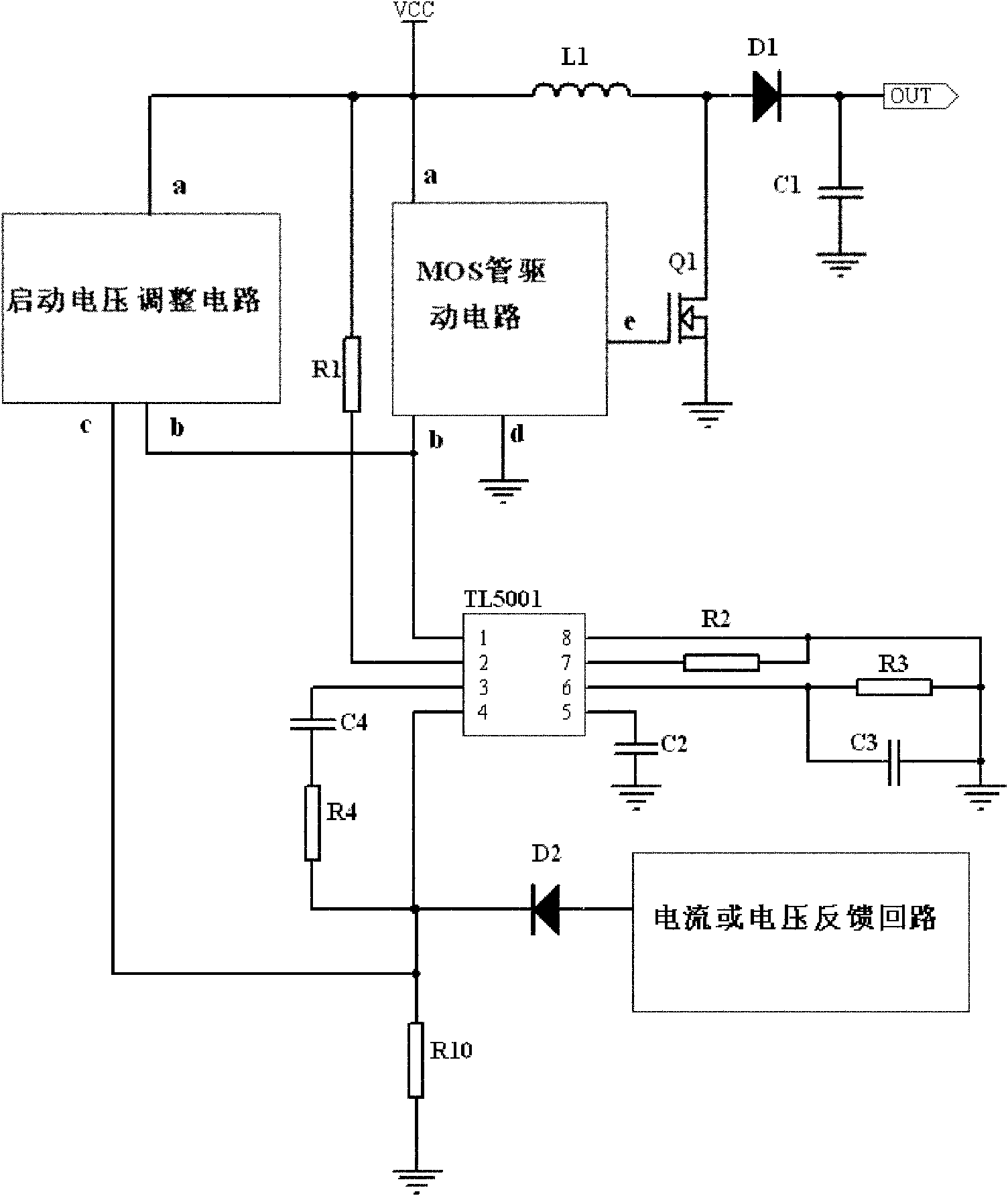
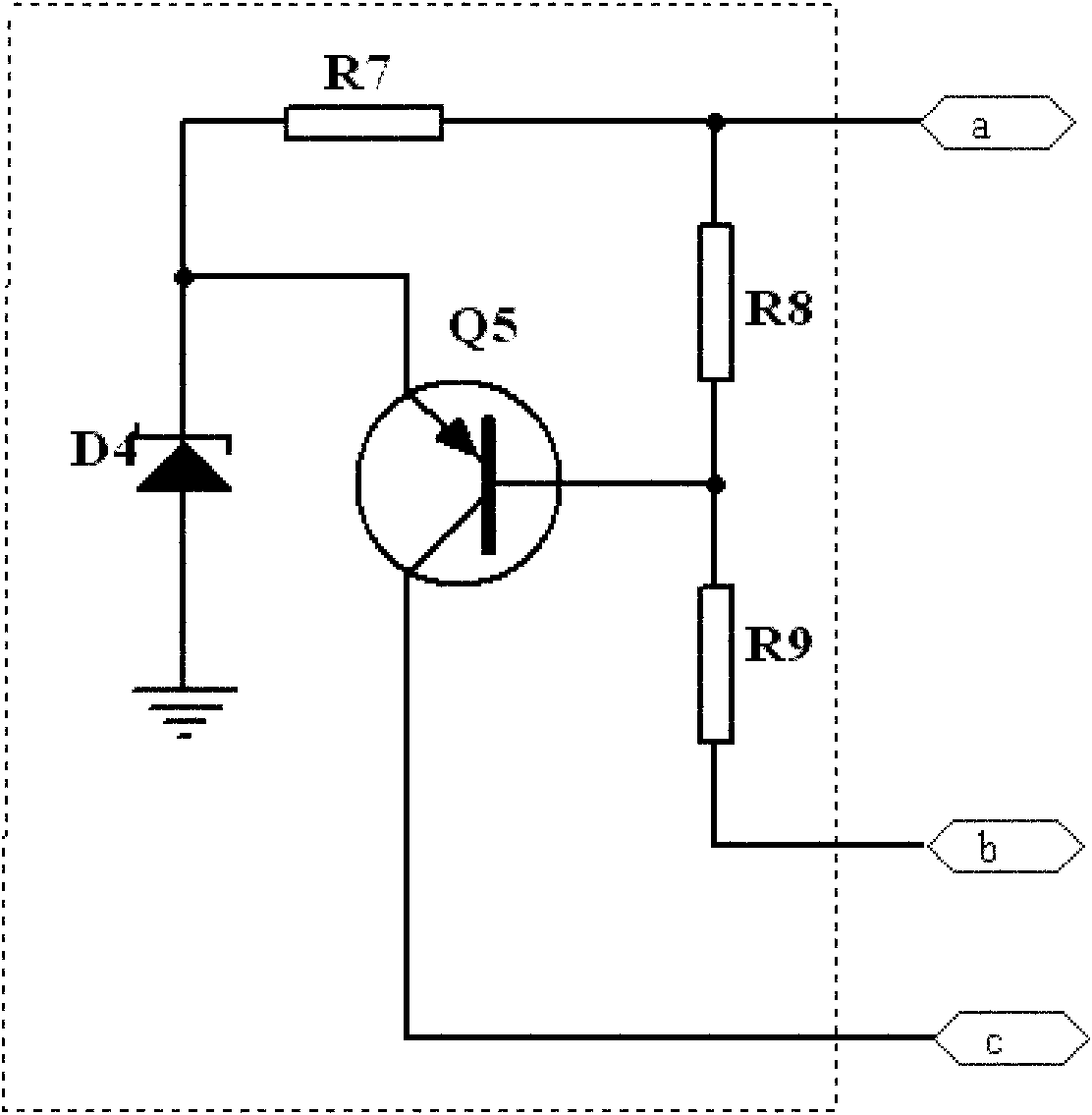
[0022] Such as figure 2 and image 3 As shown, the BOOST circuit with adjustable startup voltage includes a power supply VCC, a BOOST circuit module, a TL5001 chip, and a startup voltage adjustment module. The BOOST circuit module includes an inductor L1, a first diode D1, a first NMOS transistor Q1 and The first capacitor C1, one end of the inductor L1 is connected to the power supply VCC, the other end is connected to the anode of the diode D1 and the drain of the first NMOS transistor Q1, the source of the first NMOS transistor Q1 is grounded, and the cathode of the diode D1 is connected to the drain of the first NMOS transistor Q1. The first capacitor C1 is connected , the other end of the first capacitor C1 is grounded, the negative pole of the diode D4 is connected to one end of the tenth resistor R10 and then connected to pin 4 of the TL5001 chip, and the other end of the tenth resistor R10 is grounded. The start-up voltage adjustment module includes, The seventh re...


PUM


Abstract

The invention discloses a BOOST circuit with an adjusting starting voltage, comprising a BOOST circuit module, an TL5001 chip, a starting voltage adjusting module and a metal-oxide-semiconductor field effect transistor (MOSFET) drive circuit module, wherein the starting voltage adjusting module comprises a seventh resistor R7, an eighth resistor R8, a ninth resistor R9, a fourth voltage-stabilizing diode D4 and a fifth triode Q5. According to the BOOST circuit, by designing the starting voltage adjusting module, the starting power supply voltage of the whole BOOST circuit is improved to the required voltage value, so that the circuit starts working when the input power supply voltage reaches over a set voltage section and stops working after the input power supply voltage is lower than the set voltage, further the starting input current is reduced and the phenomenon that the circuit is locked can be avoided. Meanwhile, by designing the MOSFET drive circuit module, the circuit is simple in design and feasible, has high drive efficiency and low cost and solves the problems that a drive circuit of the TL5001 has a complex structure and high cost in the BOOST circuit.

Description

technical field [0001] The invention relates to the field of electronic technology, in particular to the application of a TL5001 control chip in a BOOST circuit (switching DC boost circuit, which is characterized in that its output voltage can be higher than its input voltage), and is especially suitable for the field of automotive electronics. Background technique [0002] TL5001 is a switching DC / DC control chip launched by TI (Texas Instruments) in the early stage. The pin diagram of the chip is as follows: figure 1 shown. Its operating voltage range is 3.6V-40V, and the highest frequency is as high as 500KHz. It can be used as a PWM control chip, a BUCK circuit (step-down conversion circuit), and a BOOST circuit control chip. As a result, TI has launched the automotive-grade control chip TL5001-Q, which enables it to play a role in the rapidly developing field of automotive electronics. [0003] In the application of TL5001 in BOOST circuit, there are two technical dif...

Claims


Application Information

Patent Timeline
IPC IPC(8): H02M3/155H02M1/36
Inventor 夏盛
Owner HASCO VISION TECHNOLOGY CO LTD
Why Eureka
Try Eureka