Sampling circuit and sampling method for phase winding current of switched reluctance motor

A technology of switched reluctance motor and sampling circuit, which is applied in the direction of electronic commutator, etc., can solve the problems of Hall sensor phase difference, temperature characteristics and frequency response characteristics, and achieve real-time sampling, high sensitivity and low price.

Active Publication Date: 2011-05-04
NANTONG SHENGYANG ELECTRIC CO LTD +1
View PDF4 Cites 6 Cited by
  • Summary
  • Abstract
  • Description
  • Claims
  • Application Information

AI Technical Summary

Problems solved by technology

[0004] Purpose of the invention: In order to overcome the deficiencies in the prior art, the present invention provides a sampling circuit of the phase winding current of the switched reluctance motor with simple structure and low cost, which solves the phase difference, temperature characteristics and frequency response of the Hall sensor. Poor characteristics and other problems; Another object of the present invention is to provide a sampling method of the phase winding current of the switched reluctance motor, so as to realize accurate and real-time measurement of the phase winding current of the switched reluctance motor
The sampling resistor is a low temperature coefficient sampling resistor

Method used


Image

  • Sampling circuit and sampling method for phase winding current of switched reluctance motor
  • Sampling circuit and sampling method for phase winding current of switched reluctance motor
  • Sampling circuit and sampling method for phase winding current of switched reluctance motor

Examples


Embodiment 1

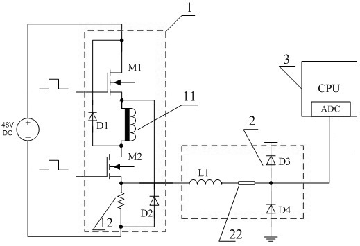
[0020] Example 1: In figure 1 Based on the circuit configuration shown, as figure 2 As shown, when both the first MOS transistor M1 and the second MOS transistor M2 are turned on, the switched reluctance motor is in the excitation mode. At this time, the externally provided 48V DC drive power supply, the first MOS transistor M1, and the motor A-phase winding 11 , the second MOS tube M2, and the manganin resistor 12 form a current loop. The excitation voltage signal at both ends of the manganin resistor 12 is transmitted from the connection point between the source of the second MOS transistor M2 and the manganin resistor to the filter circuit 2 in the direction indicated by the arrow in the figure, and then passed through the inductance L1 and the zero-ohm resistor 22 to the The ADC of the processor 3 implements resistance sampling of the winding current. The inductance L1 in the filter loop 2 can effectively filter out high-frequency signals, and the parasitic inductance p...

Embodiment 2

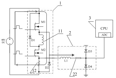
[0021] Example 2: In figure 1 Based on the circuit configuration shown, as image 3 As shown, when the first MOS transistor M1 is turned off and the second MOS transistor M2 is turned on, the switched reluctance motor is in the freewheeling mode. At this time, the A-phase winding 11, the second diode D2, the manganin resistor 12, and the second The two MOS transistors M2 form a current loop. The freewheeling voltage signal at both ends of the manganin resistor 12 is transmitted from the connection point between the source of the second MOS transistor M2 and the manganin resistor to the filter circuit 2 in the direction indicated by the arrow in the figure, and then passed through the inductance L1 and the zero-ohm resistor 22 to be transmitted to the ADC31 of the processor 3 to realize the resistance sampling of the winding current. The inductance L1, the zero-ohm resistor 22, the third diode D3 and the fourth diode D4 in the filter circuit 2 still have the same functions as...

Embodiment 3

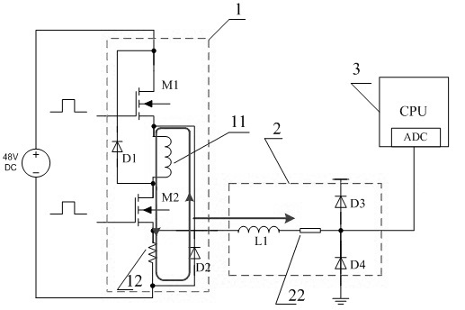
[0022] Example 3: In figure 1 Based on the circuit configuration shown, as image 3As shown, when the first MOS transistor M1 and the second MOS transistor M2 are cut off at the same time, the motor is in the recirculation mode. At this time, the first diode D1, the A-phase winding 11, the second diode D2 and the external 48V DC power supply A loop is formed. At this time, the current in the winding flows back to feed the DC power supply. No current flows through the zero-ohm resistor 22, and the processor 3 cannot obtain the corresponding current signal. However, since the motor at this time has completed the commutation from phase A to phase B, that is, it has switched to the sampling, processing and analysis of the current signal of phase B in the current sampling circuit of phase B, and the post-processing algorithm of the system has also been completed at this time. The value of the A-phase current signal is no longer needed, so it can fully meet the current sampling req...


PUM


Abstract

The invention discloses a sampling circuit and sampling method for phase winding current of a switched reluctance motor. The sampling circuit is connected with a phase winding of the switched reluctance motor in series, and comprises a current sampling circuit, a filter circuit and a processor, wherein the current sampling circuit also comprises a sampling resistor; under the working modes of excitation and follow current of the switched reluctance motor, the sampling resistor converts the phase winding current into a voltage signal, and the voltage signal is transferred to the processor for analysis after being processed by the filter circuit; and under the backflow working mode, no current passes through the sampling resistor, the phases are changed in the switched reluctance motor, and the sampling processing step of the next phase winding current is carried out. The sampling circuit for the phase winding current of the switched reluctance motor has the characteristics of low price, strong practicality and high sensitivity, is nearly not influenced by environmental temperature, and can convert the phase winding current to the voltage signal without loss in real-time so as to achieve the real-time sampling of the winding phase current.

Description

technical field [0001] The invention discloses a motor control circuit and method, in particular to a sampling circuit and a sampling method for phase winding current of a switched reluctance motor. Background technique [0002] The structure of the switched reluctance motor is simple and firm, the operation is reliable, and the efficiency is high. The inrush current phenomenon that occurs when the induction motor starts; the speed range is wide, the control is flexible, and the four-quadrant operation can be easily realized. It has strong regenerative braking capability and has high efficiency in a wide range of speed and power. It is conducive to energy saving and consumption reduction; it can work at extremely high speed; it can run without phase, and has strong fault tolerance. At present, the application of switched reluctance motors in military and civilian industries has achieved some results, but there are still some problems to be further studied and solved, mainly...

Claims


Application Information

Patent Timeline
Patent Type & Authority Applications(China)
IPC IPC(8): H02P6/14
Inventor 徐申孙大鹰何文文钟锐孙伟锋陆生礼时龙兴
Owner NANTONG SHENGYANG ELECTRIC CO LTD
Why Eureka
Try Eureka