
Plasma display panel

A plasma and display panel technology, applied in the direction of AC plasma display panels, discharge tubes, electrical components, etc., can solve problems such as difficulty in achieving low voltage effect, shortened service life of PDP, unstable chemical properties, etc., and achieve good image display performance , the effect of long service life

Inactive Publication Date: 2011-05-04
PANASONIC CORP
View PDF2 Cites 0 Cited by
  • Summary
  • Abstract
  • Description
  • Claims
  • Application Information

AI Technical Summary

Problems solved by technology

[0010] However, compared with MgO, CaO, SrO, BaO, etc. are chemically unstable and easily react with moisture or carbon dioxide remaining in the air or in the panel to form hydroxides or carbonates
The problem is that once this compound is formed, the secondary electron emission coefficient of the protective layer will drop, making it difficult to achieve the desired level of low-pressure effect
Therefore, although the use of materials with higher secondary electron emission coefficients than before has been studied, only MgO has been put into practical use, and sufficient low pressure and high efficiency have not yet been achieved.
[0012] In addition, in the case of using a material other than MgO as the protective layer, since the resistance to ion impact is low, the sputtering amount of gas generated during PDP driving increases.
Therefore, there is a problem that the service life of the PDP is shortened.

Method used


Image

  • Plasma display panel
  • Plasma display panel
  • Plasma display panel

Examples


no. 1 Embodiment approach

[0060] Next, specific examples of the PDP of the present invention will be described using the drawings.

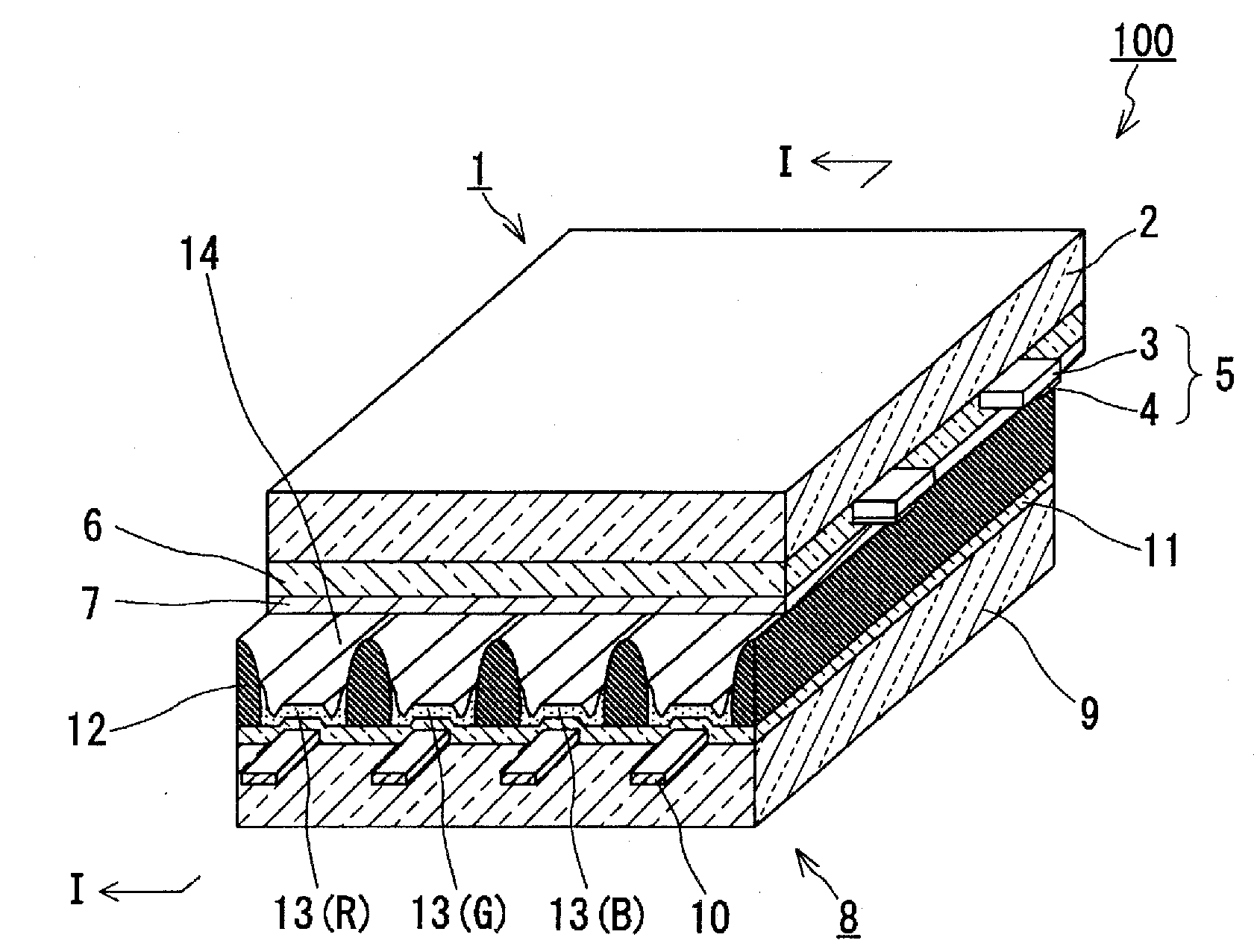
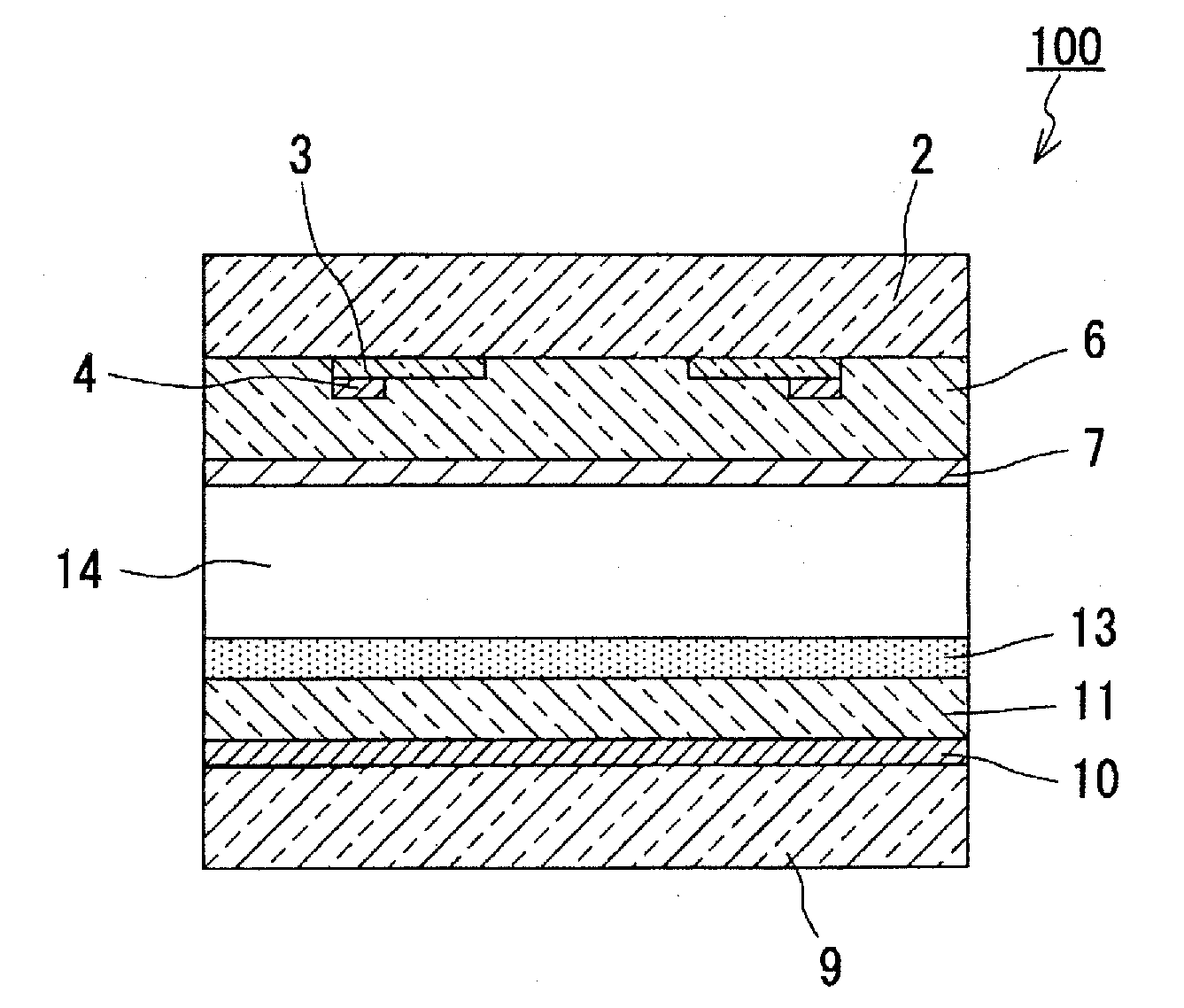
[0061] figure 1 and figure 2 An example (first embodiment) of the PDP of the present invention is shown in . figure 1 is an exploded perspective view of the PDP100. figure 2 is the longitudinal section view of the PDP100 (along figure 1 Sectional drawing of line 1-1).

[0062] like figure 1 and 2 As shown, the PDP 100 has a front panel 1 and a rear panel 8 . A discharge space 14 is formed between the front panel 1 and the rear panel 8 . The PDP is an AC surface discharge type PDP, except that the protective layer 7 is made of the above compound (made from SrCeO 3 , BaCeO 3 The structure is the same as that of the PDP of the conventional example except that one or more substances selected among them, or a crystalline oxide composed of a solid solution of these substances are used as the electron releasing material.

[0063] The front panel 1 includes: a front g...

no. 2 Embodiment approach

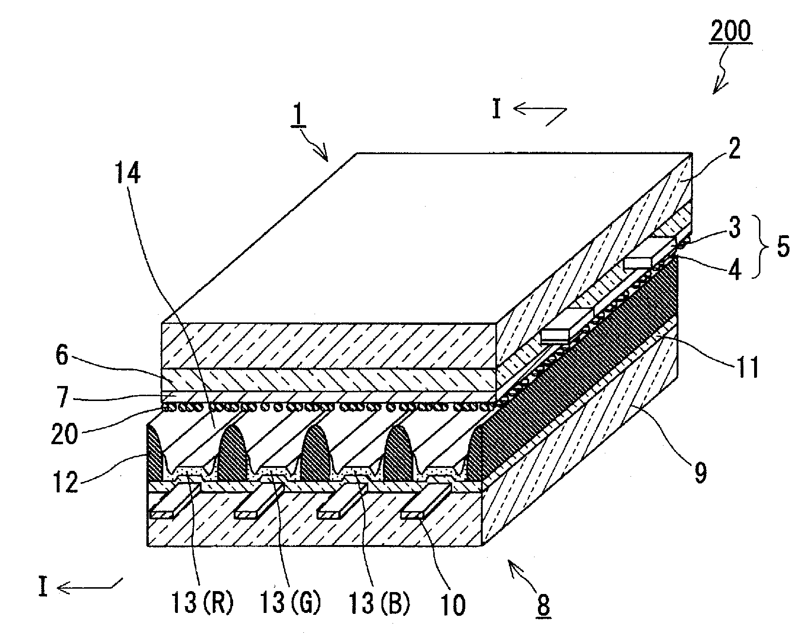
[0074] below, in image 3 and Figure 4 Another example (second embodiment) of the PDP of the present invention is shown in . image 3 is an exploded perspective view of the PDP200. Figure 4 is the longitudinal section view of the PDP200 (along image 3 sectional view of the I-I line).

[0075] The PDP 200 has the same structure as the PDP 100 except that the protective layer 7 is made of MgO and the compound powder 20 is arranged on the protective layer 7 in the form of particles. In PDP 200 , compound powder 20 also faces discharge space 14 and is arranged so as to face discharge space 14 .

[0076] Also in PDP 200 having such a structure, the same excellent image display performance as PDP 100 can be achieved and the effect of low-power driving can be achieved. In addition, the use of the protective layer 7 made of MgO also has various characteristics of the layer 7 (protection effect and long life of the dielectric layer 6 realized by good ion impact resistance perfo...


PUM


Abstract

Disclosed is a plasma display panel which is capable of exhibiting good image display performance at a low driving voltage. Specifically, a protective layer (7) is formed on the surface of a front plate (1), on which a display electrode (5) is provided, so as to face a discharge space (14), using either SrCeO3 and / or BaCeO3 or a crystalline oxide that is composed of a solid solution of SrCeO3 and BaCeO3. By using SrCeO3 and / or BaCeO3 or a crystalline oxide composed of a solid solution of SrCeO3 and BaCeO3, chemical stability can be improved without significantly decreasing the secondary electron emission efficiency. By using these compounds, a PDP is able to have a lower driving voltage when compared with a PDP using MgO.

Description

technical field [0001] The present invention relates to a plasma display panel (PDP), in particular to an improved technique for the surrounding material of a protective layer. Background technique [0002] Among thin display panels, a plasma display panel (hereinafter referred to as PDP) has been put into practical use due to its features such as easy enlargement, high-speed display, and low cost, and is rapidly popularizing. [0003] The structure of the common PDP that is currently being put into practical use is that a plurality of electrodes (display electrode pairs or address electrodes) arranged regularly are arranged on two opposing glass substrates composed of a front substrate and a back substrate, respectively. A dielectric layer such as low-melting point glass is arranged on the glass substrate to cover these electrodes. A phosphor layer is provided on the dielectric layer of the rear substrate. A MgO layer is provided as a protective layer on the dielectric la...

Claims


Application Information

Patent Timeline
Patent Type & Authority Applications(China)
IPC IPC(8): H01J11/02H01J9/02H01J11/12H01J11/40
CPCH01J11/12H01J11/40
Inventor 井上修浅野洋奥井弥生奥山浩二郎
Owner PANASONIC CORP
Learn More