Condenser

A technology of a condenser and a condensing section is applied to the field of built-in condensers, which can solve problems such as the influence of heat transfer efficiency, and achieve the effects of improving the convective heat transfer coefficient in the tube, improving the refrigeration efficiency, and improving the radiation heat transfer coefficient.

Inactive Publication Date: 2011-05-11
XI AN JIAOTONG UNIV
View PDF13 Cites 23 Cited by
  • Summary
  • Abstract
  • Description
  • Claims
  • Application Information

AI Technical Summary

Problems solved by technology

However, the channel size of this patent is more than 3mm, and the heat transfer process of the "line" contact of the built-in condenser has not been completely changed, and the heat transfer efficiency is affected to a certain extent.

Method used


Image

  • Condenser
  • Condenser
  • Condenser

Examples


Embodiment 1

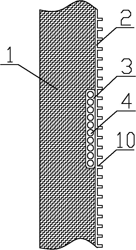
[0024] Example 1: see figure 1 , 3, this embodiment includes a heat dissipation backplane 2 and a number of porous microchannel heat exchange flat tubes 3 closely attached to the inside of the heat dissipation backplane 2 through thermally conductive silicone grease. The outer surface of the heat dissipation backplane 2 can be set to increase the heat exchange area The expanded fin 10 of the present invention uses thermally conductive silicone grease to reduce the contact thermal resistance. The thermal insulation foam layer 1 presses several porous microchannel heat exchange flat tubes 3 to the inside of the heat dissipation back plate 2. The porous microchannel The hot flat tube 3 has a plurality of parallel channels 4 with a circular cross section, a square cross section or a special cross section with an equivalent diameter of 0.8-1.2 mm along the same fluid flow direction. In order to enhance the heat exchange, the present invention can also add internal teeth in the parall...

Embodiment 2

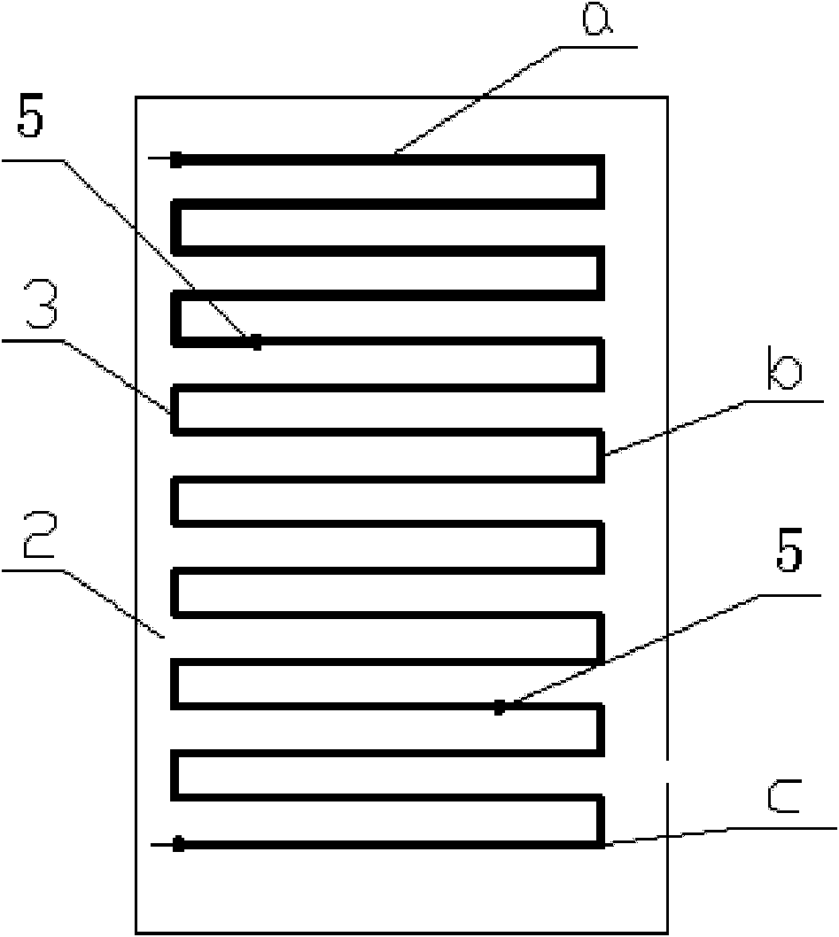
[0027] Example 2: see Figure 4 , This embodiment includes a heat dissipation backplane 2 and a number of porous microchannel heat exchange flat tubes 3 tightly attached to the inside of the heat dissipation backplane 2 through thermally conductive silicone grease. The thermal insulation foam layer 1 connects the plurality of porous microchannel heat exchange flat tubes 3 Press tightly to the inside of the heat dissipation back plate 2. The porous micro-channel heat exchange flat tube 3 has several circular cross-sections, square cross-sections or irregular cross-sections parallel to the same fluid flow direction with an equivalent diameter of 0.8-1.2mm. Channel 4. The porous microchannel heat exchange flat tubes 3 of the superheated cooling section a, the two-phase cooling section b and the supercooled condensing section c of the condenser are arranged in parallel and horizontally, and each section is arranged on both sides of the porous microchannel heat exchange flat tubes 3 ...

Embodiment 3

[0028] Example 3, see Figure 5 In this embodiment, the superheated cooling section a, the two-phase condensing section b, and the supercooling cooling section c of the condenser composed of porous microchannel heat exchange flat tubes 3 are arranged vertically in parallel. Other connections are the same as in Example 2.

[0029] See Figure 4 , 5, the high-temperature and high-pressure refrigerant vapor from the compressor first enters the distribution pipe 6, under the action of the baffle 8, enters the porous microchannel flat tube condenser 3, and then enters the collector 7, because the refrigerant is superheated vapor at this time , The specific volume is larger, so more porous micro-channel flat tube condenser 3 is used to cool to the saturated gas, and the position of the baffle 8 in the distribution pipe 6 and the collecting pipe 7 is changed, and fewer porous micro-channel flat tubes are used. The tubes are arranged in parallel to ensure that the refrigerant has a suffi...


PUM


Abstract

The invention discloses a condenser which is composed of a porous micro through heat exchange flat tube, a corresponding connecting header and a heat dissipation back plate arranged at one side of the heat exchange flat tube. In the invention, the structure is compact, the heat exchange efficiency is high, the aluminum flat tube is adopted, thus the condenser is more advantageous than the existing copper heat exchange tube in the aspect of economical efficiency, and the condenser is suitable for the fields such as refrigeration, chemical engineering, energy source, heat exchange and the like. The condenser is characterized in that on the one hand, since the porous micro channel flat tube structure is adopted, the coefficient of heat transfer in the tube is improved, and simultaneously the flow resistance of a refrigerant in the tube is reduced; and on the other hand, the contact type of the condenser and the side wall of the heat dissipation back plate is surface contact, so that contact thermal resistance is reduced, the average temperature of the side wall of the heat dissipation back plate is improved, and the heat exchange between the side wall of the back plate and the ambient air is strengthened, namely the condensing effect is strengthened, thus, when the lengths of pipes are the same, the quantity of the condenser can be increased, or when the heat exchange quantities are the same, the length of the pipes can be reduced, therefore the condenser is more compact, simultaneously the material consumption is reduced, and the condenser has a certain advantage in the aspect of economical efficiency.

Description

Technical field [0001] The invention belongs to the field of common household refrigeration, and particularly relates to a built-in condenser suitable for refrigeration equipment such as general refrigerators or freezers. Background technique [0002] Refrigerators and freezers are the only all-day power-consuming appliances among household appliances. While bringing people a comfortable life, they also consume a lot of electricity. The introduction of the "Limited Value of Electricity Consumption and Energy Efficiency Grades of Household Refrigerators (GB12021.2-2008)" in China has already mandated technological transformation and innovation on refrigerators, hoping to be more energy-efficient. From the perspective of the refrigeration system, the condenser undertakes the task of dissipating heat outward, and its heat load is the largest, so it is one of the main components that need to strengthen energy-saving research. The existing refrigerator condenser is mainly built-in pl...

Claims


Application Information

Patent Timeline
Patent Type & Authority Applications(China)
IPC IPC(8): F25B39/04
CPCF25B39/04F25B40/02F25B40/04F28F1/022F28F2270/00
Inventor 刘迎文刘冈云童欢徐升华胡露露
Owner XI AN JIAOTONG UNIV
Why Eureka
Try Eureka