Method for manufacturing hose connector core

A technology for hose joints and manufacturing methods, which is applied in the field of hose joint core manufacturing, can solve the problems of complex processing, reduced processing costs, and increased total costs, and achieves tight arrangement of crystal phase structure, reduced loss of raw materials, and reduced turning The effect of processing

Inactive Publication Date: 2011-05-25
YUYAO HANGYI AUTOMOBILE PARTS
View PDF5 Cites 30 Cited by
  • Summary
  • Abstract
  • Description
  • Claims
  • Application Information

AI Technical Summary

Problems solved by technology

Using single-station cold heading production, not only the inner hole of the hose joint core cannot be punched out, but also the two ends can not be flattened, and the total length is not easy to control, which increases the difficulty of subsequent car repair processing
Although part of the material is saved by single-station cold heading, drilling is still required, and the processing cost is not greatly reduced. Moreover, the inner hole is not very rough because it is processed by a drill bit. To achieve a good finish, a reamer must be used. The knife is processed again, so the cost will naturally go up again, so many manufacturers do not use this method, or some products use this method
In addition, using this method to produce, there are many subsequent processing procedures, complex processing, high production cost, low efficiency, and the manpower and material resources invested are too large, and it does not meet the national policy requirements for energy conservation and emission reduction.
[0004] The production of straight bar or broken material requires processes such as material breaking, primary and secondary drilling, stripping knife, and fine turning repair. Not only are there many procedures, but the processing speed is slow, and more waste materials such as material heads and tails are generated. , resulting in waste of materials, waste of labor, low output and other disadvantages, which increase the total cost and cannot meet the requirements of market competition, high quality and low cost.

Method used


Image

  • Method for manufacturing hose connector core
  • Method for manufacturing hose connector core
  • Method for manufacturing hose connector core

Examples


Embodiment Construction

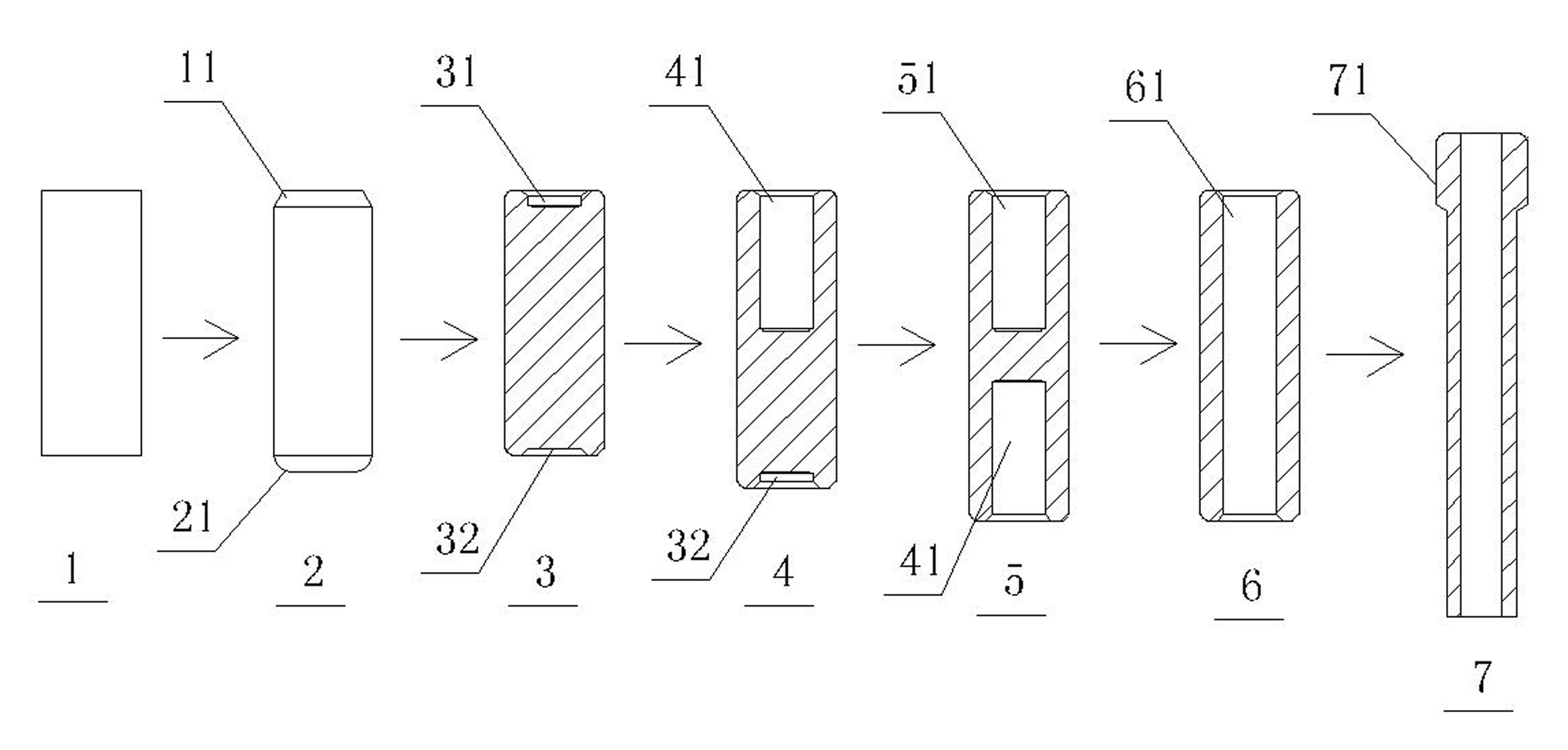
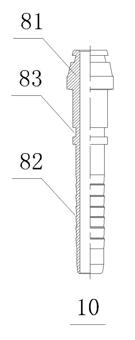
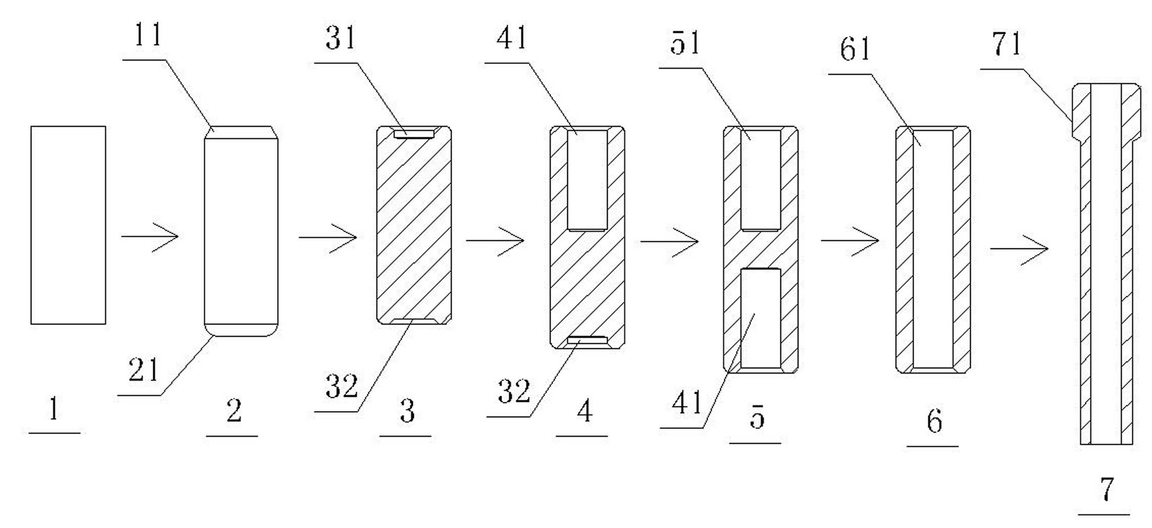
[0020] Refer to attached picture. The present invention adopts the round wool as the raw material. First, the round wool is subjected to spheroidizing annealing treatment, and then the round wool after the spheroidizing and annealing is subjected to phosphate film surface treatment, and then finely drawn and sized, and then the finely drawn and sized The round finished material is cut into individual hose joint core blanks 1, and then the hose joint core blank 7 is made by cold pier machine according to the following six-station cold pier method:

[0021] (1) Automatically feed the hose joint core blank into the mold of the first station of the cold heading machine with clips, level one end of the hose joint core blank, and form a natural chamfer 11 at the corner, after turning 180 °, the hose joint core blank is automatically sent into the mold of the second station of the cold heading machine with a clip, the other end of the hose joint core blank is leveled, and a natural c...


PUM


Abstract

The invention provides a method for manufacturing a hose connector core, which comprises the following steps of: performing spheroidizing annealing on a wire rod blank material serving as a raw material; performing phosphate coating surface treatment on the wire rod blank material subjected to spheroidizing annealing; performing fine drawing sizing, and cutting a wire rod finished product material subjected to fine drawing sizing into single hose connector core blank materials; and manufacturing the blank of the hose connector core by using a seven-station cold heading method and a cold heading machine. The wire rod material is used for replacing a straight bar material and a broken material, so that the requirement of multi-station cold heading continuous production can be met, and the loss of a material head and a material tail is reduced; stations are reasonably designed, so that the physical property and the quality of a product are improved, and the product has good surface appearance; a material part is easily subjected to plastic deformation in the cold extrusion process, and the loss of a die is low; and finish machining production speed is doubled.

Description

technical field [0001] The invention relates to the field of a method for manufacturing a hose joint core. Background technique [0002] Nowadays, with the continuous progress of industrial economy at home and abroad, the use of hoses for plastic machines, excavators, and automobiles has developed rapidly, making the demand for hose connectors used at both ends of hoses very large. It has also created a huge hose joint market, and the hose joint core as a part of the hose joint has a very large market. However, at present, the main processing method of the hose joint core is to complete the processing with straight bar material, single-station cold heading and other processes, which is not only slow, but also has the disadvantages of high processing cost, large energy consumption, and high total cost. [0003] The hose joint core is in the shape of a long round tube, with a connector connected to the nut at one end, and a connecting pipe section that is connected to the hos...

Claims


Application Information

Patent Timeline
Patent Type & Authority Applications(China)
IPC IPC(8): B23P15/00
Inventor 张金清吴黄覆董成友
Owner YUYAO HANGYI AUTOMOBILE PARTS
Why Eureka
Try Eureka