Biomass energy combustor

A biomass energy and burner technology, applied in the direction of biofuels, combustion methods, combustion equipment, etc., can solve the problems of inability to produce charcoal in the middle, and the quality of charcoal is low, so as to improve the combustion-supporting effect, increase the contact surface, and increase the contact the effect of time

Inactive Publication Date: 2011-05-25
杜克镛 +2
View PDF8 Cites 12 Cited by
  • Summary
  • Abstract
  • Description
  • Claims
  • Application Information

AI Technical Summary

Problems solved by technology

[0005] The purpose of the present invention is to solve the problem that the existing biomass combustion furnace cannot produce charcoal in the middle, or the quality of the charcoal is low, and to provide an automatic charcoal discharge burner with good charcoal quality

Method used


Image

  • Biomass energy combustor
  • Biomass energy combustor
  • Biomass energy combustor

Examples


Embodiment 1

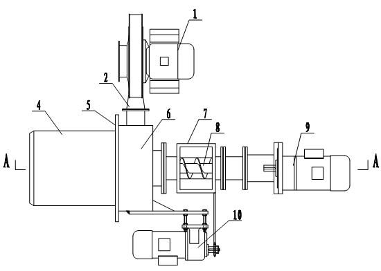
[0030] Embodiment 1: a kind of biomass energy burner, such as Figure 1 to Figure 4 shown.

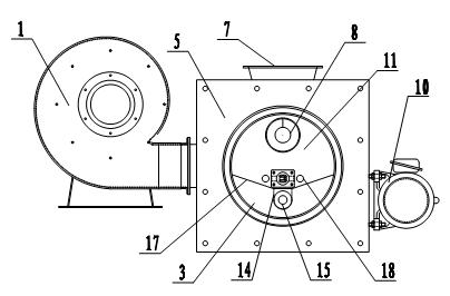
[0031] This device comprises burner base body 4, and burner base body 4 is horizontal cylinder type, as figure 1 , figure 2 , image 3As shown, the burner base 4 has a double-layer structure, the inner layer is the combustion chamber 11, the outer layer is the secondary air distribution chamber 3, the secondary air distribution chamber 3 surrounds the outside of the combustion chamber 11, the top of the combustion chamber 11 is an arc top, and passes through The top wall of the combustion chamber separates the combustion chamber 11 from the secondary air distribution chamber 3, and the bottom of the combustion chamber 11 is provided with an air distribution plate 17 and is separated from the secondary air distribution chamber 3 by the air distribution plate 17, as Figure 4 As shown, the air distribution plate 17 is provided with an air distribution hole 19 . Such as image 3 As ...

Embodiment 2

[0034] Embodiment 2: A kind of biomass energy burner that preheats combustion-supporting air, such as Figure 5 , Figure 6 shown. A layer of preheating chamber 20 is arranged on the outer periphery of the burner base 4 , and a plurality of cold air inlets 21 are opened on the circumference of the preheating chamber 20 , and the preheating chamber 20 is connected with the fan air inlet 22 . The rest of the structure in this embodiment is the same as in Embodiment 1.

[0035] Due to heat conduction, the outer wall of the burner base 4 usually has a higher temperature, even reaching more than 100 degrees. The combustion-supporting air enters the preheating chamber 20 from the cold air inlet 21, and the heat of the outer wall of the burner base 4 is used for preheating. From the fan 1 to the air distribution chamber 6, not only the heat lost during combustion is reused, but also the heat insulation effect between the burner base 4 and the environment is achieved.

[0036] The ...

Embodiment 3

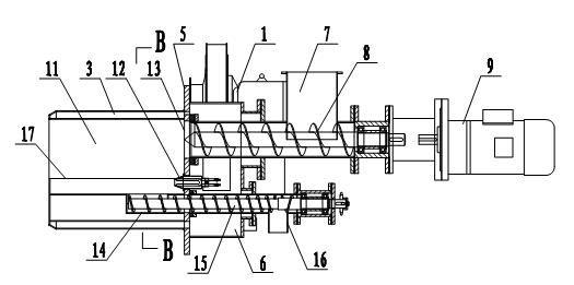
[0037] Embodiment 3: a kind of feed compression biomass energy burner, such as Figure 7 shown. The pitch of the feed auger 8 helical blades decreases continuously with the conveying direction, and the ratio of the pitches at both ends is 4:1. The rest of the structure of this embodiment is the same as that of Embodiment 1.

[0038] When the biomass fuel to be burned is bamboo chips, wood chips, straw, etc., if the feeding auger with equal pitch is used, because the fuel is relatively loose, there is a large gap in the fuel delivery process, and the smoke in the combustion chamber is easy to flow from The gap overflows, and because the fuel is entrapped with air, the fuel is easily ignited at the inlet of the combustion chamber, and burns all the way to the hopper, causing serious consequences. Therefore, when using such loose fuel, it is necessary to The fuel is compressed to make the fuel structure more compact, and at the same time, the air trapped in the fuel gap is exha...


PUM


Abstract

The invention relates to a combustor, in particular to a biomass energy combustor capable of automatically discharging carbon, which solves the problem of incapability of discharging carbon in the midway or low discharged carbon quality of the traditional biomass combustor. The biomass energy combustor comprises a combustion chamber which is provided with a feeding hole and a carbon discharging hole. The biomass energy combustor is characterized in that the carbon discharging hole is provided with a carbon discharging packing auger, and the thread pitches of helical blades of the packing auger are gradually reduced along the carbon discharging direction. The invention has the advantages that a combustion substrate can be compressed while discharging carbon so that the combustion substrateis further carbonized and the carbon content of the product is increased; air is introduced to the combustion chamber from a plurality of angles through a main air port and air distribution holes, thus, the direction of air flow in the combustion chamber is changed, the contact time and the contact area of combustion-supporting air and combustion materials are increased, and the combustion-supporting effect is improved; and the combustion-supporting air is repeatedly preheated by utilizing the heat of the combustion chamber, thereby the heat is reasonably utilized, and the heat loss is reduced.

Description

technical field [0001] The invention relates to a burner, in particular to a biomass energy burner capable of automatically producing charcoal. technical background [0002] Biomass energy, as an important direction of new energy development, has received more and more attention. Bamboo chips, wood chips, straw, etc. produced in industrial and agricultural production belong to biomass energy. Some people put the above-mentioned bamboo chips, wood chips, straw, etc. The most direct way to use biomass energy is to release energy through combustion. At the same time, the charcoal produced during the combustion process is used as an important raw material to make fertilizers. Carbon-containing fertilizers can improve soil structure. It can also be used to make various products such as activated carbon. People have designed various burners for the combustion of biomass energy. If the fuel in the burner burns excessively and the biomass energy is completely burned, no charcoal wi...

Claims


Application Information

Patent Timeline
Patent Type & Authority Applications(China)
IPC IPC(8): F23B40/00F23L5/00F23L5/02F23L15/00C10B53/02
CPCF23B40/06C10B53/02F23B60/02Y02E50/14C10B49/02Y02E50/10Y02P20/129F23B40/00F23K3/14
Inventor 杜克镛钟哲科罗伯特·弗拉纳根
Owner 杜克镛
Why Eureka
Try Eureka