Industrial furnace capable of realizing thermal shift and atmospheric uniformity of gas flow field

An industrial furnace and heat displacement technology, applied in the direction of furnace, furnace type, lighting and heating equipment, etc., can solve the problems of energy waste, low energy saving level, unsatisfactory thermal efficiency, etc., and achieve uniform and no dead angle, reduce heat treatment energy Consumption, the effect of improving the level of cleaner production

Active Publication Date: 2012-12-19
HANGZHOU JINZHOU TECH CO INC
View PDF2 Cites 0 Cited by
  • Summary
  • Abstract
  • Description
  • Claims
  • Application Information

AI Technical Summary

Problems solved by technology

Existing solutions usually use devices such as stirring fans, centrifugal fans, and heat return hoods to enhance gas convection heat transfer. However, the effect of convective heat transfer at high temperatures above 700°C is negligible, and it is impossible to truly evenly heat the workpiece and prevent local decarburization. the goal of
[0004] For large-scale continuous and step-by-step heat treatment furnaces whose furnace length is much longer than the furnace width and height, the traditional energy-saving measure is to use waste heat outside the furnace and other systems, because a considerable part of the energy has been wasted in the process of heat exchange and utilization. dropped, the energy saving level is relatively low
[0005] The heat transfer technology in the furnace has been ideally realized in the single-layer and double-layer furnace invention patents authorized by our company: ZL200610053067.7, ZL200810120771.9; The long-distance thermal energy displacement of the furnace at the discharge port is realized by hot air blowers and hot air pipes, and the thermal efficiency is still unsatisfactory

Method used


Image

  • Industrial furnace capable of realizing thermal shift and atmospheric uniformity of gas flow field
  • Industrial furnace capable of realizing thermal shift and atmospheric uniformity of gas flow field

Examples


Embodiment Construction

[0020] The present invention will be further explained below in conjunction with the drawings and embodiments:

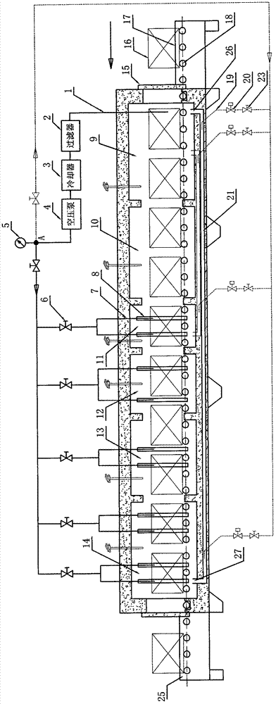
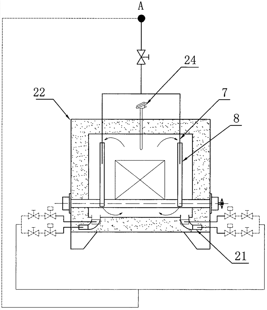
[0021] Such as figure 1 , figure 2 As shown, the industrial furnace that realizes the thermal displacement of the gas flow field and the uniform atmosphere includes a furnace body 22, a thermocouple 24, a feeding table 17, a discharging table 25, a driving roller 18 and a furnace door 15, in the front section of the furnace The preheating section 10 is connected through the suction pipe 1, the filter 2, the cooler 3, and the input end of the air pressure pump 4. The output end of the air pressure pump 4 passes through the regulating valve 6 and is connected to the cooling area at the back of the furnace. A set of upper and lower convective injection pipes 7 are connected. The output end of the air pressure pump 4 is connected with a pressure gauge 5. The upper and lower convective injection pipes 7 are installed in the corresponding upper and lower convection guide pi...


PUM


Abstract

The invention relates to an industrial furnace capable of realizing the thermal shift and atmospheric uniformity of a gas flow field, which comprises a furnace body, thermocouples, a feeding table, a discharge table, driving rollers and furnace doors. A preheated section on the front section of a hearth is connected with the input end of an air compression pump by an air suction pipe, a filter and a cooler; one path of the output end of the air compression pump is communicated with a group of vertical convection injection pipes arranged in a cooling area on the rear section of the hearth; andthe vertical convection injection pipes run through the furnace body to be arranged in corresponding vertical convection guiding tubes to form jet flow structures. The industrial furnace has the advantages that: the technology can solve technical difficulties in the furnace gas flowing, circulation, thermal energy shift and the like of a large furnace and reduce temperature differences by temperature control; and the thermal energy of the furnace section required to be cooled is shifted to the furnace section required to be heated according to a thermal treatment process curve, thereby greatly reducing thermal treatment energy consumption, simultaneously avoiding a great amount of heat being discharged out of the furnace, improving the cleaning production level and improving the working environment of workers.

Description

Technical field [0001] The invention relates to the field of industrial furnace equipment, in particular to an industrial furnace that realizes thermal displacement of gas flow field and uniform atmosphere. Background technique [0002] In all kinds of large-scale industrial furnaces and kilns, due to the limitation of furnace geometry and heating source distribution, there is a large temperature gradient in the vertical direction of the furnace, and there is a temperature difference in different parts of the workpiece due to the difference in the angle between the heat radiation source and the workpiece The uneven heating affects the metallographic structure, hardness and strength. [0003] Due to the uneven furnace atmosphere and the existence of dead corners, local decarburization problems often occur. It is difficult to achieve uniform heating and no local decarburization of the workpiece surface for workpieces with large or complex geometries. The existing solutions usually ...

Claims


Application Information

Patent Timeline
Patent Type & Authority Patents(China)
IPC IPC(8): F27B9/02F27B9/04F27B9/30
Inventor 韩志根
Owner HANGZHOU JINZHOU TECH CO INC
Why Eureka
Try Eureka