Plug and play optical fiber gyro and total station combination orientation method

A fiber optic gyroscope, plug-and-play technology, applied in Sagnac effect gyroscopes, instruments, measuring devices, etc., can solve the problems of the horizontal axis error of the total station, the long cantilever of the connection device, and the difficulty of installation, etc. The influence of orientation accuracy is eliminated, the operation process is simple, and the effect of eliminating the influence of accuracy

Active Publication Date: 2011-06-15
SOUTHEAST UNIV
View PDF4 Cites 4 Cited by
  • Summary
  • Abstract
  • Description
  • Claims
  • Application Information

AI Technical Summary

Problems solved by technology

[0015] This invention has the following deficiencies: firstly, the condition that "the fiber optic gyroscope is installed on the telescope of the total station in such a way that the angle between its axis and the transverse axis of the total station does not exceed 5 degrees" requires very high requirements for the design and processing of the connecting device , in order to prevent deformation, high requirements are put forward for the material selection of the connecting device; secondly, the calculation result using formula (1) is greatly affected by the installation error angle, and is also affected by the transverse axis error of the total station; However, with the installation method of this invention, due to the small installation error limit and the long cantilever of the connecting device, it is difficult to install at the work site
[0016] There will be a previously unknown gyroscope zero bias error in the measured value after each power-on of the fiber optic gyroscope, which will bring errors to the calculation of the azimuth angle of the fiber optic gyroscope axis; In total station work, what needs to be obtained is the azimuth angle of the collimation axis of the total station, so there is a connection error angle between the fiber optic gyro axis and the collimation axis of the total station

Method used


Image

  • Plug and play optical fiber gyro and total station combination orientation method
  • Plug and play optical fiber gyro and total station combination orientation method
  • Plug and play optical fiber gyro and total station combination orientation method

Examples


Embodiment Construction

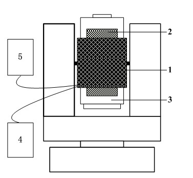
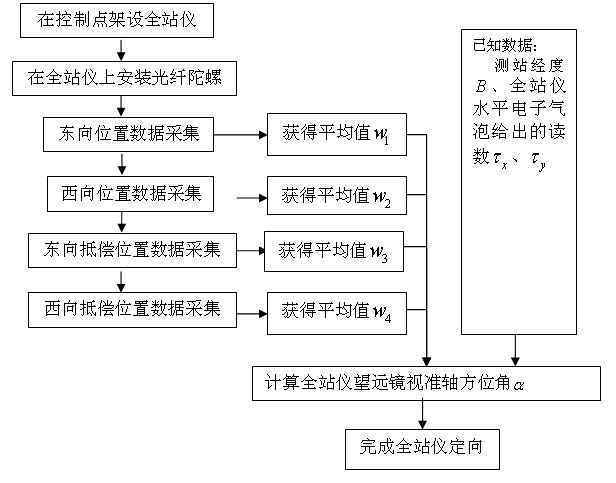
[0035]The present invention utilizes the earth's rotation angular velocity sensitive to the optical fiber gyroscope to orient the total station, and the specific technical solution is: level the centering total station at the control point of the known point longitude B, and fix the optical fiber gyroscope to the On the total station telescope, connect the power supply and computing equipment with the fiber optic gyroscope, and drive the total station telescope to the east and west positions with a horizontal difference of 180 degrees by horizontally rotating the sighting part of the total station. The positions are then rotated vertically by 180 degrees of the total station telescope to drive the fiber optic gyroscope to the east compensation position and the west compensation position. In the above four positions, the fiber optic gyroscope is used to measure the earth's rotation angular velocity for no less than n times. The measurement data calculates the true azimuth α of t...


PUM


Abstract

The invention discloses a plug and play optical fiber gyro and total station combination orientation method, which is a hardware combination method, an operation flow and a calculation formula applied to surveying and mapping work. The method comprises the following steps of: leveling and centering the total station on a control point of a known point position longitude B; fixedly connecting the optical fiber gyro to a telescope of the total station by using a locking device; connecting a power supply and computer equipment with the optical fiber gyro; horizontally rotating an alidade of the total station to drive the telescope of the total station to an east orientation position and a west orientation position which have an included angle of 180 degrees respectively; vertically rotating the telescope of the total station 180 degrees at the east orientation position and the west orientation position respectively to drive the optical fiber gyro to an east orientation compensation position and a west orientation compensation position; measuring the rotational angular velocities of the earth by using the optical fiber gyro at the four positions respectively; and calculating a true azimuth of a collimation axis of the total station at the east orientation position by using measurement data. In the method, the structure is simple, connection error calibration is not needed to be performed, and the orientation of the total station can be realized under the condition of only one control point by performing simple operation.

Description

technical field [0001] The invention relates to an orientation method, in particular to a combined orientation method of a plug-and-play optical fiber gyroscope and a total station for surveying and mapping. The invention belongs to the technical field of mechanical surveying and mapping. Background technique [0002] In surveying and mapping work, when using the total station for point measurement or stakeout, it is necessary to first determine the azimuth of the total station's collimation axis, that is, to carry out the total station orientation. The current total station orientation method is to erect the total station on a known control point, look back at another known control point that is far apart, and obtain the azimuth of the total station's line-of-sight axis by inverse calculation of the coordinates of the two points. GPS positioning technology has the advantage of not needing inter-point line-of-sight during point measurement, and has become the main means of c...

Claims


Application Information

Patent Timeline
Patent Type & Authority Applications(China)
IPC IPC(8): G01C1/00G01C19/72
Inventor 于先文王庆
Owner SOUTHEAST UNIV
Why Eureka
Try Eureka