Cr series high-temperature solar selective absorbing coating and preparation method thereof

A technology for absorbing coatings and solar energy, applied in the field of solar energy utilization, can solve the problems of low process deposition rate, long production cycle, complex process, etc., and achieve the effects of low price, low emissivity, and simple preparation process

Active Publication Date: 2011-06-22
北京天瑞星光热技术有限公司
View PDF5 Cites 31 Cited by
  • Summary
  • Abstract
  • Description
  • Claims
  • Application Information

AI Technical Summary

Problems solved by technology

However, processes such as double-target or multi-target co-sputtering and RF sputtering have low deposition rates, long production cycles, complex processes, and high costs.

Method used


Image

  • Cr series high-temperature solar selective absorbing coating and preparation method thereof
  • Cr series high-temperature solar selective absorbing coating and preparation method thereof

Examples


preparation example Construction

[0025] A method for preparing a Cr-based high-temperature solar selective absorption coating, comprising the following steps:

[0026] Step 1: preparing the first infrared emitting layer on the substrate;

[0027] Using pure metal target intermediate frequency magnetron sputtering method, the substrate is made of stainless steel, firstly prepare the first protective coating of the first infrared emission layer on the substrate, the pure metal target is Cr target or Al target, and Ar and O 2 The mixed gas is prepared as sputtering gas. Before sputtering, pre-pump the vacuum chamber to a background vacuum of 4×10 -3 ~5×10 -3 Pa, into the inert gas Ar as the sputtering atmosphere, adjust the sputtering distance to 130 ~ 150mm, adjust the sputtering pressure to 3 × 10 -1 ~4×10 -1 Pa. Turn on the power supply of the sputtering target of the pure metal target, adjust the sputtering voltage to 380-450V, and the sputtering current to 8-10A, and prepare the first layer of protecti...

Embodiment

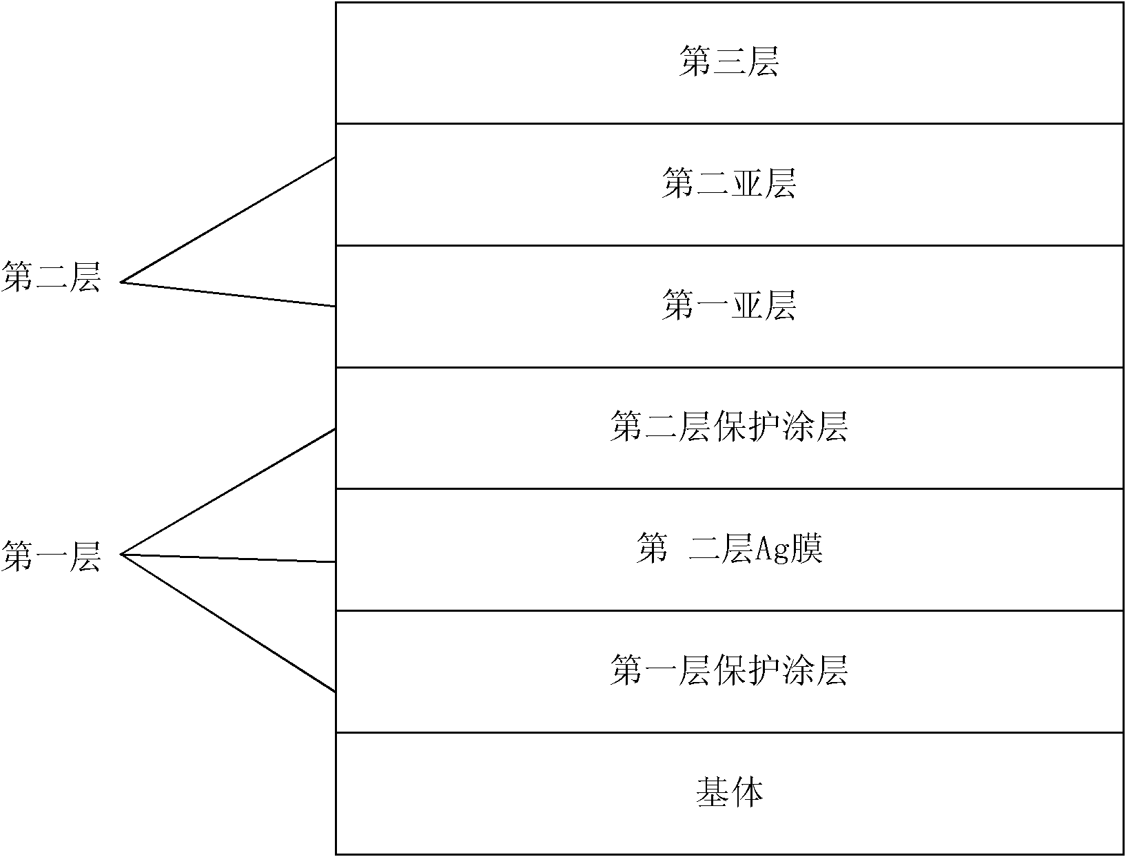
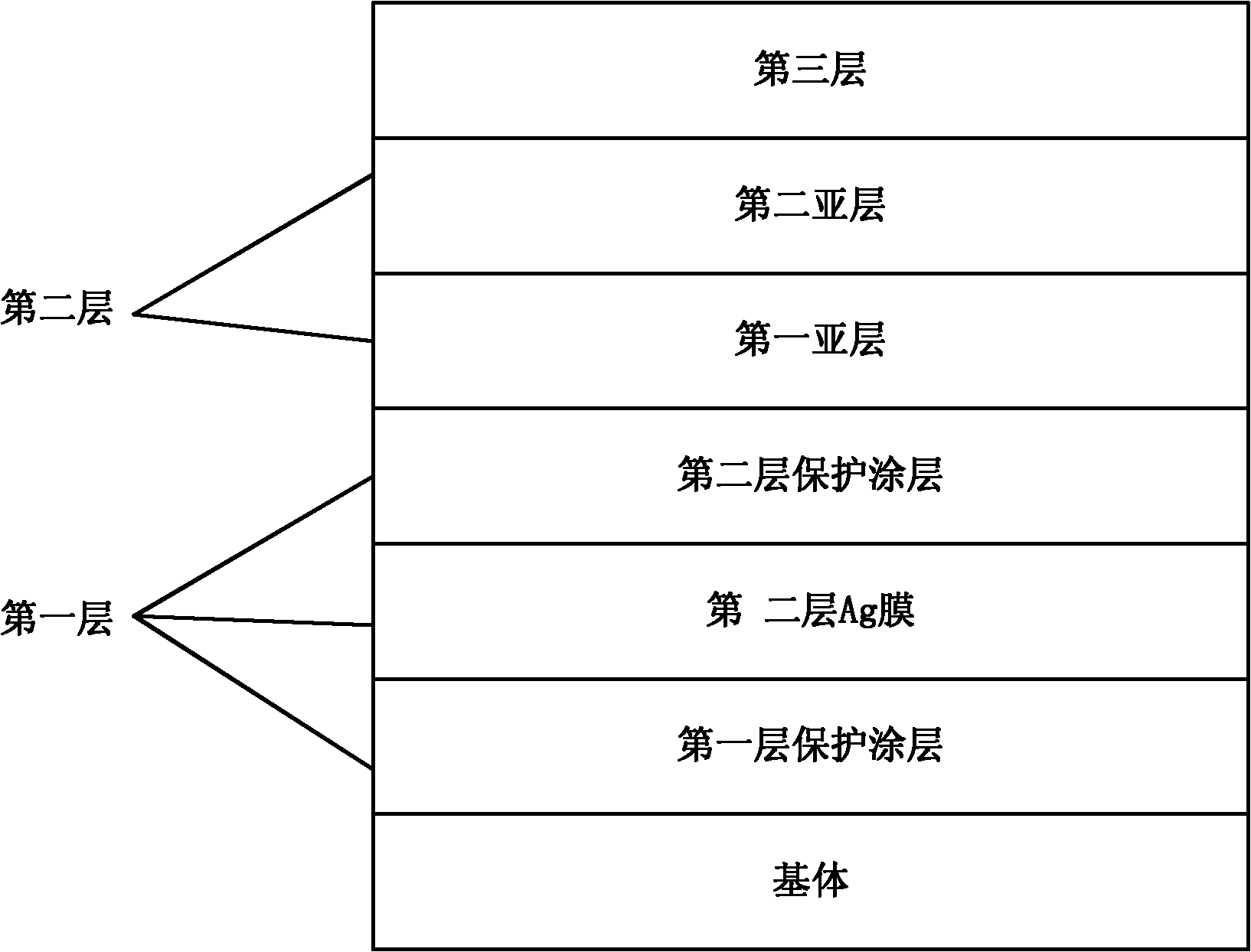
[0038] Prepare a Cr-based high-temperature solar energy selective absorption coating, including three coatings, namely the first infrared reflection layer, the second absorption layer, and the third anti-reflection layer. The thickness of the first layer is 100-250nm, and the second layer is The total thickness of the layers is 110-150 nm, wherein the thickness of the first sub-layer is 60-80 nm, the thickness of the second sub-layer is 50-70 nm, and the thickness of the third layer is 30-50 nm. The preparation steps are as follows:

[0039] Step 1: preparing the first infrared emitting layer on the substrate;

[0040] An Al target with a purity of 99.99% and an Ag target with a purity of 99.99% are selected, and stainless steel is used as the base material. First prepare the first protective coating of the first infrared emission layer on the substrate, and pre-evacuate the vacuum chamber to 4.5×10 before sputtering. -3 ~5×10 -3 Pa, through the inert gas Ar and O 2 The mi...


PUM

PropertyMeasurementUnit
thicknessaaaaaaaaaa
thicknessaaaaaaaaaa
thicknessaaaaaaaaaa

Abstract

The invention discloses a Cr series high-temperature solar selective absorbing coating and a preparation method thereof. The coating consists of an infrared reflection layer, an absorption layer and an antireflection layer in turn from the bottom to the surface, wherein the first infrared reflection layer consists of three membranes; the middle infrared reflection layer is a Ag membrane of which the upside and downside are plated with a protective film that is any one of a chromic oxide (Cr2O3) film and an aluminum oxide (Al2O3) film respectively; the second absorption layer has two sub-layer structures both of the which are AlCrN+AlCr films, the volume percentage of the first sub-layer AlCr is greater than that of the second sub-layer AlCr; and the third antireflection layer is any one of Cr2O3 film and Al2O3 film. The preparation method comprises the steps of: preparing the infrared emission layer on the substrate surface by adopting a pure metal target magnetron sputtering process; preparing the second absorption layer on the first layer by adopting a Cr target and Al target middle-frequency magnetron sputtering process; and preparing the third antireflection layer on the second layer by adopting a metal target middle-frequency magnetron sputtering process.

Description

technical field [0001] The invention relates to the technical field of solar energy utilization, in particular to a Cr-based high-temperature solar selective absorption coating and a preparation method thereof. Background technique [0002] The solar spectrum selective absorption coating has a high absorption rate in the visible-near-infrared band and a functional film with a low emissivity in the infrared band, which is the key to improving the efficiency of light-to-heat conversion for solar collectors. With the continuous development of solar heat utilization requirements and technology, the application range of solar collector tubes has been developed from low temperature applications (≤100°C) to medium temperature applications (100°C-350°C) and high temperature applications (350°C-500°C). Meet the requirements of medium and high temperature applications such as seawater desalination and solar power generation. The selective absorption coating used for the heat collecti...

Claims


Application Information

Patent Timeline
Patent Type & Authority Applications(China)
IPC IPC(8): F24J2/48C23C14/04C23C14/35B32B9/04B32B15/00
CPCF24J2/4652F24J2/487Y02E10/40F24S70/225F24S70/25F24S70/30
Inventor 刘雪莲张秀廷陈步亮范兵王静卢铁军
Owner 北京天瑞星光热技术有限公司
Why Eureka
Try Eureka