
Controllable method for preparing atomic force microscope needlepoint with carbon nano tube

An atomic force microscope and carbon nanotube technology, which is applied in scanning probe microscopy, scanning probe technology, gaseous chemical plating, etc. High-resolution, easy-to-use effects

Inactive Publication Date: 2011-06-29
北京五泽坤科技有限公司
View PDF0 Cites 15 Cited by
  • Summary
  • Abstract
  • Description
  • Claims
  • Application Information

AI Technical Summary

Problems solved by technology

When the traditional tapered AFM needle tip is worn, its radius of curvature will become larger and the resolution will be reduced. The imaging of the AFM is greatly affected by the probe. Therefore, with the development of nanotechnology, a higher performance AFM is required. emergence of probes

Method used


Image

  • Controllable method for preparing atomic force microscope needlepoint with carbon nano tube
  • Controllable method for preparing atomic force microscope needlepoint with carbon nano tube
  • Controllable method for preparing atomic force microscope needlepoint with carbon nano tube

Examples


Embodiment Construction

[0021] The invention uses the electrochemical reduction method to deposit nickel nanoparticles of a certain size on the tip of the atomic force microscope, and then uses the PECVD method to grow a single carbon nanotube on the nickel nanoparticle, and develops a process for preparing the tip of the atomic force microscope from the carbon nanotube.

[0022] The technical solutions of the present invention will be described in further detail below in conjunction with the accompanying drawings and embodiments.

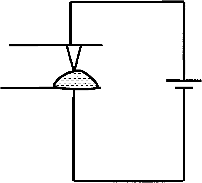
[0023] see figure 1 , figure 1 is a schematic diagram of an atomic force microscope tip. The atomic force microscope tip in the figure is a Si tip. The tip is small in size and light in weight, making it easy to image with an atomic microscope. The length of its tip is tens of micrometers.

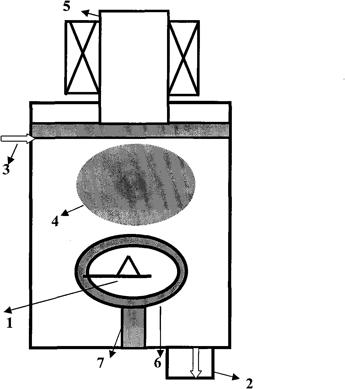
[0024] see figure 2 , figure 2 is a schematic illustration of the deposition of nickel nanoparticles on the tip of an atomic force microscope. The steps of electrochemical re...


PUM


Abstract

The invention provides a process for preparing an atomic force microscope needlepoint by using single carbon nano tube. The process comprises the following steps of: depositing a metal nanoparticle on the microscope needlepoint by an electrochemical reduction method, placing the microscope needlepoint on which the metal nanoparticle is deposited upward, and performing fixed-point and oriented growth on the single carbon nano tube on the microscope needlepoint by a plasma enhanced chemical vapor deposition method. The obtained atomic force microscope needlepoint assembled with the single carbon nano tube can be used for atomic force microscope imaging.

Description

technical field [0001] The invention relates to a nanostructured atomic force microscope tip and a preparation method thereof, in particular to an atomic force microscope tip assembled with a single carbon nanotube and a preparation method thereof. Background technique [0002] Carbon nanotubes (Carbon nanotubes, CNTs) have attracted people's attention since they were discovered by Japanese scientist Iijima in arc discharge in 1991. They have extensive applications in composite materials, nanoelectronic devices, field emission displays, hydrogen storage materials, and probes. Potential application prospects. Carbon nanotubes are a new type of material with a complete molecular structure at the nanometer scale. They have a large aspect ratio, excellent electrical conductivity, thermal conductivity, good chemical stability and mechanical strength. The diameter of carbon nanotubes is very small, generally 2 to 20nm. At the same time, carbon nanotubes have incomparable flexibil...

Claims


Application Information

Patent Timeline
IPC IPC(8): G01Q60/38C23C16/26C23C16/513C23C16/455C25D7/00
Inventor 不公告发明人
Owner 北京五泽坤科技有限公司
Features
  • Generate Ideas
  • Intellectual Property
  • Life Sciences
  • Materials
  • Tech Scout
  • Unparalleled Data Quality
  • Higher Quality Content
  • 60% Fewer Hallucinations
Learn More