Sampling method and device

A sampling device and sample technology, applied in the field of gas chromatographic analysis, can solve problems such as laborious, high risk factors, and complex chromatographic flow paths, and achieve the effects of saving adjustment time, ensuring personnel safety, and simplifying chromatographic flow paths

Inactive Publication Date: 2011-07-20
FOCUSED PHOTONICS
View PDF5 Cites 13 Cited by
  • Summary
  • Abstract
  • Description
  • Claims
  • Application Information

AI Technical Summary

Problems solved by technology

[0005] 1. The sampling device quantitative loop and the enrichment tube are installed at the same position in the GC flow path. When analyzing samples with different concentrations, the sampling device needs to be replaced manually, which is time-consuming and labor-intensive. Especially when the portable GC is used for on-site emergency monitoring, it is necessary to replace the quantitative loop. and the time loss caused by the enrichment tube is huge;
[0006] 2. When replacing the quantitative loop / enrichment tube, it is easy to damage the device;
[0007] 3. Both the quantitative loop and the enrichment tube need to be installed in the GC flow path to facilitate the analysis of the gas to be tested at different concentrations. This often replaces the quantitative loop and the enrichment tube, which makes the chromatographic flow path complicated and increases the dead volume
[0010] 1. Time-consuming and labor-intensive
[0011] The gas to be tested is enriched through the enrichment tube with a preset enrichment time, and then the measurement results are obtained through sample injection, separation and analysis; according to the measurement results, the enrichment time is fine-tuned, and then the gas to be tested is passed into the enrichment tube, and finally get the measurement results until a satisfactory result is achieved; in this process, it may be necessary to fine-tune the enrichment time several times to achieve a satisfactory result, which takes a long time;
[0012] 2. High cost
[0013] Corresponding measurements are required when fine-tuning the enrichment time, and these pre-sequence measurements will waste more samples and increase the cost of measurements;
[0014] 3. High risk factor
[0015] If the object to be tested is a toxic and harmful gas, it will cause damage to the operator's body if exposed to the environment for a long time;
[0016] 4. Timing delay
[0017] The concentration of the analyte changes with time. If the enrichment time is adjusted multiple times, the concentration information at a certain moment cannot be obtained in time.

Method used


Image

  • Sampling method and device
  • Sampling method and device
  • Sampling method and device

Examples


Embodiment 1

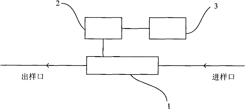
[0057] see figure 1 , a sampling device, comprising a sample inlet, a sample outlet, an enrichment tube 1, a heating element 2 and a temperature control unit 3;

[0058] The enrichment pipe 1 is a section of stainless steel pipe filled with adsorbent; the shape of the enrichment pipe 1 can be, but not limited to, cubic, spherical and barrel-shaped, and this embodiment is barrel-shaped;

[0059] Described adsorbent can be TenaxTA (2,6 diphenyl p-phenylene ether polymer resin) or TenaxGR (2,6 diphenyl p-phenyl ether polymer resin+30% graphite) or Carbotrap (graphitized carbon black) or Carbotrap C ( Graphitized carbon black) or Carboxen569 (carbon molecular sieve) or CarbosieveSIII (carbon molecular sieve); Present embodiment is TenaxTA;

[0060] The heating element 2 can be an independent heating device, or the enrichment tube itself, and the heating element 2 can be heated by energizing it; in this embodiment, the heating element 2 is an independent heating device;

[0061] ...

Embodiment 2

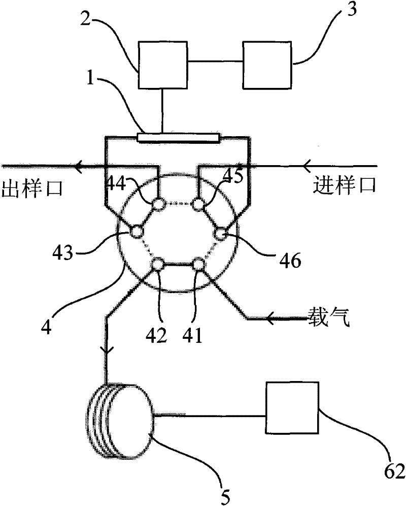
[0071] see figure 2 , a sampling device, different from the sampling device described in embodiment 1: the sampling device also includes a chromatographic analysis unit, and the chromatographic analysis unit includes a valve 4, a chromatographic column 5 and a chromatographic detector 62;

[0072] The valve 4 can be a six-way valve, an eight-way valve or a ten-way valve, etc., and it is a six-way valve in this embodiment; the valve 4 has six interfaces 41, 42, 43, 44, 45, 46;

[0073] The interface 45 is connected with the sample inlet; the interface 44 is connected with the sample outlet;

[0074] When the valve 4 is in the sampling position, the port 41 communicates with the port 42, the port 43 communicates with the port 44, and the port 45 communicates with the port 46; the carrier gas flows into the six-way valve through the port 41, directly flows out from the port 42, and reaches the chromatographic column 5; The sample to be measured flows into the enrichment tube 1 ...

Embodiment 3

[0088] see Figure 4 , a sampling device, different from the sampling device described in embodiment 1 is:

[0089] The temperature control unit 3 is a sequential heating control unit; when setting the heating temperature of the enrichment pipe 1, the temperature duration can be set at the same time;

[0090] The sampling device also includes a detector 63; the detector 63 is connected to the sample inlet through the valve 7; the flow path formed by the valve 7 and the detector 63 is a bypass;

[0091] The detector 63 can be a thermal conductivity detector (Thermal Conductivity Detector, TCD) or a hydrogen flame ionization detector (Flame Ionization Detector, FID) or an electron capture detector (Electron Capture Detector, ECD) or a flame photometric detector ( Flame Photometric Detector, FPD) or Nitrogen-phosphorus detector (Nitrogen-phosphorus detector, NPD) or mass spectrometer detector (Mass Spectrometer Detector, MSD), this embodiment is MSD.

[0092] When the sample to...


PUM


Abstract

The invention relates to a sampling method, which comprises the following steps: a, controlling the temperature of an enriching tube according to the concentration of a sample to be tested so as to prevent the enriching tube from enriching the sample to be tested when the concentration of the sample to be tested is higher than a set value; and b, introducing the sample to be tested into the enriching tube for sampling. The invention also provides a sampling device. The invention has the advantages of simple operation, wide concentration application range, high practicality and the like.

Description

technical field [0001] The invention relates to a method and a device for sampling substances in a large concentration range, which are mainly used in the field of gas chromatography analysis. Background technique [0002] Gas chromatograph (GC) is an instrument for qualitative and quantitative analysis of unknown substances. According to different sampling methods, it can be divided into two types of instruments: syringe sampling method and sampling pump sampling method. The syringe sampling method usually analyzes It is a liquid sample, and the instrument with sampling pump injection method usually analyzes gaseous samples. [0003] The concentration of gaseous samples may vary from ppt level to ppm level. When analyzing gaseous samples with sampling pump injection instruments, in order to adapt to the analysis of substances with different concentrations, two devices, quantitative loops and enrichment tubes, are usually used for quantification. The quantitative loop is us...

Claims


Application Information

Patent Timeline
Patent Type & Authority Applications(China)
IPC IPC(8): G01N30/08
Inventor 吴文明刘立鹏郑毅
Owner FOCUSED PHOTONICS
Why Eureka
Try Eureka