Supercharge Your Innovation With Domain-Expert AI Agents!

Digital electronic fluorescent scanning voltage sensor

A voltage sensor and fluorescence scanning technology, applied in the direction of using digital measurement technology for measurement, can solve the problems of not achieving high and low potential electrical isolation, poor reliability, and small measurement range.

Inactive Publication Date: 2011-08-03
FUZHOU UNIV
View PDF6 Cites 3 Cited by
  • Summary
  • Abstract
  • Description
  • Claims
  • Application Information

AI Technical Summary

Problems solved by technology

Its advantage is to realize the optical isolation between high and low potentials, but the disadvantage is that the method of light intensity measurement is nonlinear, and is seriously affected by stress birefringence, the measurement range is small, and the reliability is poor
[0006] The active electronic type uses a capacitive voltage divider, a resistive voltage divider or an inductive voltage divider to obtain a small voltage signal. The disadvantage is that the electrical isolation between high and low potentials is not realized.
[0007] The common disadvantage of the above transformers is that only analog voltage signals can be obtained on the low-voltage side, and digital signals need to be obtained by means of analog-to-digital conversion circuits, which has become an obstacle to the full digitalization of substations.

Method used


Image

  • Digital electronic fluorescent scanning voltage sensor
  • Digital electronic fluorescent scanning voltage sensor
  • Digital electronic fluorescent scanning voltage sensor

Examples


specific Embodiment approach 2

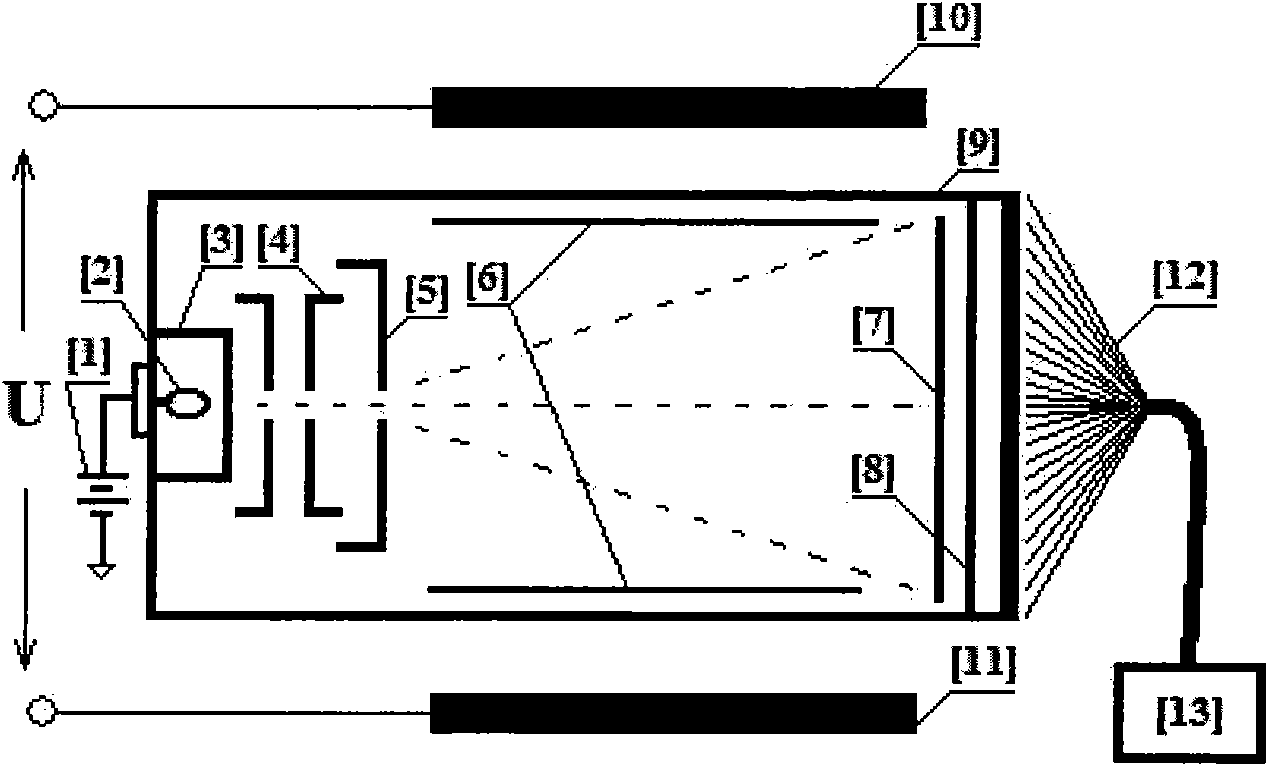
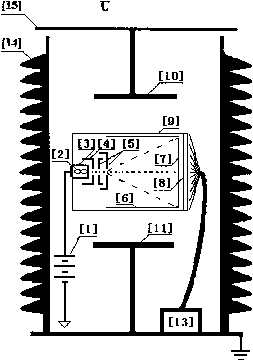
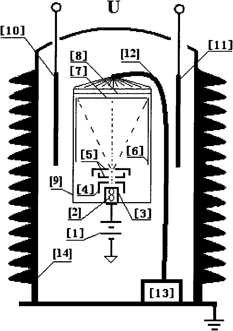
[0016] The second specific embodiment is as follows image 3 shown, consists of a filament [2], a cathode [3], a control grid [4], a focusing anode [5], an accelerating anode [6], an aluminum film [7], a phosphor layer [8], and a vacuum glass envelope [ 9] A cathode ray tube is formed, and the DC power supply is provided by [1]. [2] After being energized, [3] is heated, and electrons are emitted to form an electron beam. The voltage difference between [3] and [4] controls the size of the electron beam. At the same time, [4] and [5] form an electron lens to focus the electron beam, and the accelerating anode [6] is a graphite layer, on which a DC voltage is applied to accelerate the electrons and form a uniform equipotential space to ensure the electron beam Flying straight to the phosphor layer [8] without deviating or defocusing, the aluminum film [7] is attached to [6] to protect [8] from being damaged by ion shocks. The phosphor on [8] is bombarded by electrons and then e...


PUM


Abstract

The invention relates to a digital electronic fluorescent scanning voltage sensor based on a principle of an action of an electric field force (a voltage) on motion electrons and a digital image processing technology. An electron current beam which is subjected to heat emission by a cathode is focused and accelerated by a direct current voltage, passes through an electric field formed by a voltage to be measured in vacuum, and bombards a fluorescent powder layer for light emitting; and a fluorescent light is transmitted to a charge coupled device (CCD) / complementary metal-oxide-semiconductor transistor (CMOS) image sensor. Two polar plates which form the electric field are connected to the voltage to be measured; the electrons are bombarded to different positions on the fluorescent powder layer under the action of the electric field force between the polar plates on the electrons; the change of light emitting positions is in proportion to the size of the electric field force (the voltage); and a real-time digital voltage signal is obtained by adopting the CCD / CMOS image sensor to measure the change of positions of light emitting points. A measuring method is linear and applied to measurement of an alternating current voltage and the direct current voltage of a power system.

Description

technical field [0001] The invention relates to a digital electron fluorescence scanning voltage sensor, which is suitable for the measurement of AC and DC voltages of power systems based on the action principle of electric field force (voltage) on moving electrons and digital image processing technology. Background technique [0002] At present, there are four types of voltage transformers or sensors that can be used for high voltage measurement: electromagnetic type, capacitive type, analog photoelectric type and active electronic type. [0003] The outstanding problems of electromagnetic voltage transformer in the application of ultra-high voltage and ultra-high voltage power system are its high electrical insulation cost and low reliability. Taking into account the requirements of safety, reliability, accuracy, cost performance, etc., electromagnetic voltage transformers are not suitable for high voltage levels. [0004] Capacitive voltage transformers are based on the ...

Claims


Application Information

Patent Timeline
Patent Type & Authority Applications(China)
IPC IPC(8): G01R19/25
Inventor 徐启峰
Owner FUZHOU UNIV
Features
  • R&D
  • Intellectual Property
  • Life Sciences
  • Materials
  • Tech Scout
  • Unparalleled Data Quality
  • Higher Quality Content
  • 60% Fewer Hallucinations
Learn More