Relay

A repeater and filter technology, which is applied in the field of high-performance repeaters, can solve the problems of small dynamic range, poor stability, large intermodulation distortion and intermodulation distortion of repeaters, and achieves large dynamic range and reliable operation. High performance, reducing intermodulation distortion

Inactive Publication Date: 2011-08-03
SUZHOU INNOTION TECH
4 Cites 0 Cited by

AI-Extracted Technical Summary

Problems solved by technology

Existing repeaters have small dynamic range, large intermodulation distortion a...

Abstract

The invention discloses a relay which is characterized by comprising matchers, one-way surface acoustic wave filters and a power amplifier, wherein the input end of the relay is accessed to the first one-way surface acoustic wave filter by the first matcher; the first one-way surface acoustic wave filter is connected with the power amplifier by the second matcher; the power amplifier is connected with a second one-way surface acoustic wave filter by a third matcher; and the second one-way surface acoustic wave filter is connected with the output of the relay by the fourth matcher. The relay has the advantages of larger dynamic range, good thermostability and high working reliability, and the crosstalk and the intermodulation distortion of the relay can be lowered.

Application Domain

Radio relay systems

Technology Topic

DistortionLarge dynamic range +9

Image

  • Relay
  • Relay
  • Relay

Examples

  • Experimental program(1)

Example Embodiment

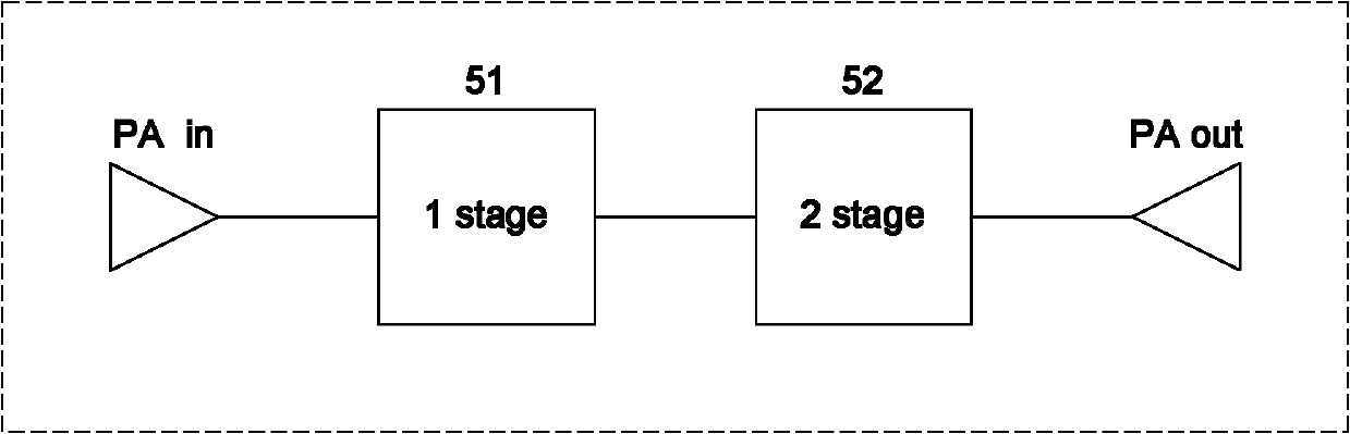
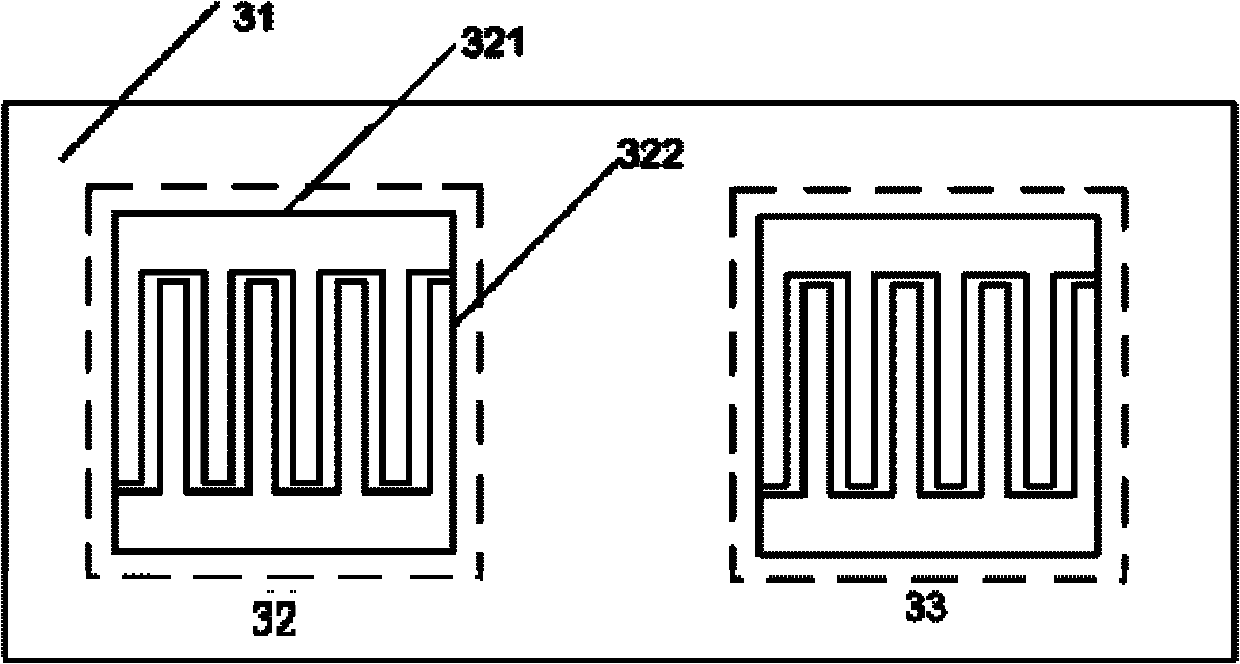
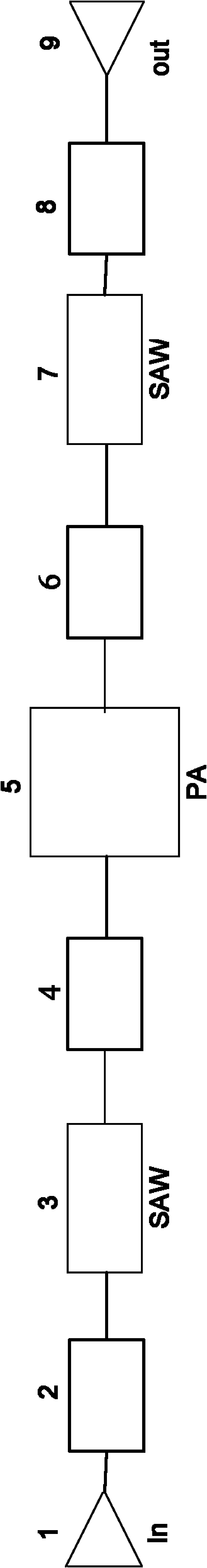
[0016] Example: such as figure 1 , 2 , 3, the input signal is input from input terminal 1, passes through matcher 2 to unidirectional bandpass surface acoustic wave filter 3, then reaches matcher 4, passes through matcher 4 to PA (Power Amplifier, power amplifier) ​​5, from PA5 The output signal passes through the matcher 6, the one-way band-pass surface acoustic wave filter 7, and the matcher 8 is output from the output port 9. The unidirectional bandpass surface acoustic wave filter 3 is composed of a substrate 31 and an input transducer 32 and an output transducer 33 on the substrate 31. The input transducer 32 is composed of electrodes 321 and finger strips 322. PA is a two-stage amplifier, 1stage51 and 2stage52 respectively.
[0017] The bandpass surface acoustic wave filter and PA in the present invention can adopt existing technical solutions. In the example of the present invention, a lithium niobate band-pass surface acoustic wave filter is used to achieve filtering. In the example of the present invention, the PA is a PA designed by Suzhou Inno Motion Company, and the number is INXGB25402300941. The PA is composed of HBT transistors, with a gain G of 30dB and a bandwidth of 80MHz. Among them, the size of the first level is 320um 2 , The second level size is 2500 um 2. The main function of the first stage is to amplify the signal, adjust the input impedance, and realize automatic gain control; the second stage further amplifies the signal to ensure a sufficiently high gain. The present invention is not limited to the specific models described in the text, and other band-pass surface acoustic wave filters and PAs that meet the requirements are also included.

PUM

no PUM

Description & Claims & Application Information

We can also present the details of the Description, Claims and Application information to help users get a comprehensive understanding of the technical details of the patent, such as background art, summary of invention, brief description of drawings, description of embodiments, and other original content. On the other hand, users can also determine the specific scope of protection of the technology through the list of claims; as well as understand the changes in the life cycle of the technology with the presentation of the patent timeline. Login to view more.

Similar technology patents

Piezoelectric type gravity meter

ActiveCN105204082Alarge dynamic rangegood linearity
Owner:谭成忠

Method for selecting image data source in optical instrument

ActiveCN102006431Alarge dynamic rangegood contrast
Owner:江苏钜芯集成电路技术股份有限公司

DC electric energy meter

InactiveCN106597091Alarge dynamic rangeImprove stability
Owner:ZHEJIANG CHINT INSTR & METER

Radio frequency receiving channel circuit for implementing satellite navigation anti-interference antenna

PendingCN107167818Alarge dynamic rangeReduce circuit complexity and power consumption
Owner:TIANJIN 764 COMM AIRMANSHIP

Classification and recommendation of technical efficacy words

  • large dynamic range
  • Reduce intermodulation distortion

Frequency Agile Filter Using a Digital Filter and Bandstop Filtering

InactiveUS20110227664A1large dynamic range
Owner:RPX CLEARINGHOUSE

Complex spectral domain optical coherence tomography method and system

InactiveCN101297750ASimple system structurelarge dynamic range
Owner:SHENZHEN POLYTECHNIC

Rock quartz accelerometer servo-circuit

InactiveCN101266260Alarge dynamic rangegood linearity
Owner:CHINA AEROSPACE TIMES ELECTRONICS CORP NO 771 RES INST

Non-linear pulse-width modulation PWM control device

InactiveCN1770934Alarge dynamic rangeImprove intuitive feeling
Owner:上海国皓电子有限公司

Stereoscopic displaying apparatus

ActiveCN101281299AReduce intermodulation distortion
Owner:ARISAWA MFG CO LTD

Linear frequency modulation radar ranging system and method based on distance

PendingCN114019492AReduce intermodulation distortionReduce difficulty
Owner:ZHONGDA TESTING (HUNAN) CO LTD
Why Eureka
Try Eureka