
Solution dehumidifying and regenerating device

A solution dehumidification and regeneration device technology, which is applied in household heating, lighting and heating equipment, space heating and ventilation, etc., can solve the problem of unfavorable heat and mass exchange between solution and humid air, reduction of mass transfer potential difference, and damage to heat transfer In order to achieve uniform distribution of solution concentration, avoid corrosion, and reduce pressure drop

Inactive Publication Date: 2011-08-10
SOUTHEAST UNIV
View PDF8 Cites 14 Cited by
  • Summary
  • Abstract
  • Description
  • Claims
  • Application Information

AI Technical Summary

Problems solved by technology

However, as the dehumidification or regeneration process proceeds, the temperature of the solution gradually increases (dehumidification process) or decreases (regeneration process), so the mass transfer potential difference between the solution and the humid air gradually decreases, which is not conducive to the relationship between the solution and the humid air. heat and mass exchange
Some use traditional plate-fin or tube-fin heat exchangers to make internal cooling or internal heating dehumidifiers, but the solution usually has a corrosive effect, so traditional heat exchanger metal materials such as aluminum and copper are easily corroded and damaged heat transfer device

Method used


Image

  • Solution dehumidifying and regenerating device
  • Solution dehumidifying and regenerating device
  • Solution dehumidifying and regenerating device

Examples


Embodiment Construction

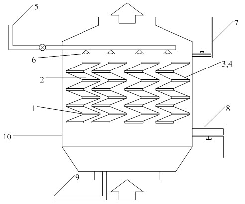
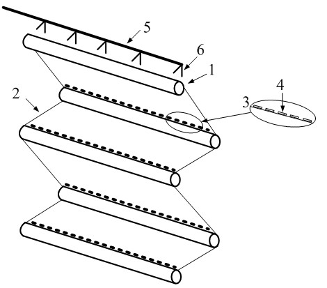
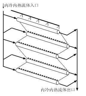
[0024] The housing 10 is equipped with a heat and mass transfer unit composed of a number of "zigzag" connected drop plates 2 and inner cooling and inner heat pipes 1, and a dehumidification solution inlet pipe 5 is provided on the upper left of the housing 10 for dehumidification. The solution is introduced and sprayed through the nozzle. The upper right of the housing 10 is provided with an internal cooling / internal heat source inlet main pipe 7 for the fluid of the cold and heat source, and the lower part is provided with an outlet pipe 8; the dehumidification solution inlet pipe 5 is provided Above the heat and mass transfer unit body, the liquid separator 6 is set on the dehumidification solution inlet pipe 5, and the dehumidification solution is evenly sprayed onto the drop plate 2 through the nozzle, and the dehumidification regeneration solution outlet pipe 9 is provided at the bottom of the shell 10 .

[0025] An overflow structure 3 is provided at the link between th...


PUM


Abstract

The invention discloses an internal cold / internal heat type solution dehumidifying and regenerating device. A plurality of zigzag connected heat and mass transfer units consisting of reducing templates (2) and internal cold / internal heat pipes (1) are arranged in a shell (10), an inlet pipe (7) is arranged above the shell, and an outlet pipe (8) is arranged below the shell; a dehumidifying solution inlet pipe (5) is arranged above the heat and mass transfer units, a solution distributor (6) is arranged on the dehumidifying solution inlet pipe (5), and the bottom of the shell (10) is provided with a dehumidifying and regenerating solution delivery pipe (9). A dehumidifying solution flows into a pipeline through a solution inlet header pipe and is sprayed to the reducing templates to be in direct contact with wet air for carrying out a heat and mass transfer process so that the purpose of air dehumidifying or solution regenerating is achieved; and internal heat / internal cold branch pipes play a role of strengthening the heat and mass transfer process, thus the solution dehumidifying and regenerating efficiency is greatly improved. The internal cold / internal heat type solution dehumidifying and regenerating device has the advantages of simple machining process, low cost and easiness in production and manufacture.

Description

technical field [0001] The invention relates to a solution dehumidification / regeneration device, and belongs to the technical field of air conditioning, solution dehumidification device / regeneration device manufacturing and heat and mass transfer enhancement in solution dehumidification air conditioners. Background technique [0002] In recent years, global environmental problems have been highlighted, and energy utilization crises have continued. The energy consumption of air-conditioning systems caused by the wide application of refrigeration and air-conditioning equipment has aroused widespread concern in the current society. Energy conservation has become an urgent requirement in the field of refrigeration and air-conditioning under the new situation. The research and application of an energy-saving air-conditioning system has become a current hot spot. [0003] The solution dehumidification air-conditioning system is a new type of energy-saving and environment-friendly ...

Claims


Application Information

Patent Timeline
Patent Type & Authority Applications(China)
IPC IPC(8): F24F3/14
Inventor 殷勇高陈瑶张小松李士强
Owner SOUTHEAST UNIV
Learn More