
SiGe matrix nanocomposite materials with an improved thermoelectric figure of merit

A nanocomposite material and matrix technology, applied in the field of nanocomposite materials, can solve problems such as insufficient efficiency

Inactive Publication Date: 2011-08-10
法国原子能与替代能源委员会
View PDF1 Cites 6 Cited by
  • Summary
  • Abstract
  • Description
  • Claims
  • Application Information

AI Technical Summary

Problems solved by technology

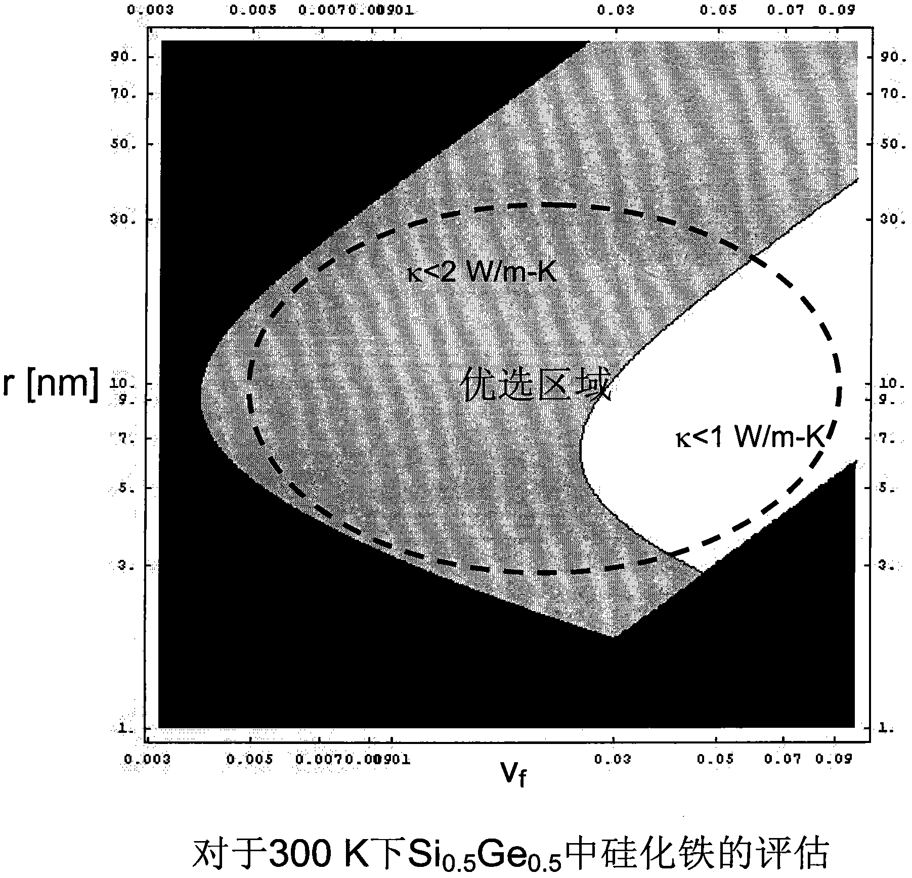
However, Shakouri's group (A. Shakouri, Nanoscale Thermal Transport and Microrefrigerators on a Chip, Proceedings of IEEE, 94, 1613 (2006)) showed that SiGe is not efficient enough for most hotspot cooling applications because room temperature ZT is only greater than 0.1

Method used


Image

  • SiGe matrix nanocomposite materials with an improved thermoelectric figure of merit
  • SiGe matrix nanocomposite materials with an improved thermoelectric figure of merit
  • SiGe matrix nanocomposite materials with an improved thermoelectric figure of merit

Examples


Embodiment Construction

[0074] Experimental part

[0075] The process is divided into two consecutive steps providing the SiGe layer and the MoSi silicide dotting on its surface. Then, these two consecutive steps were repeated several times, thereby forming a SiGe nanocomposite with MoSi inclusions.

[0076] First consecutive steps:

[0077] The SiGe nanocomposite layer was grown by reduced pressure chemical vapor deposition (RP-CVD). This precipitation technique has been used in the literature to realize superlattices (Venkatasubramanian, R. et al., Nature, Vol 413, 11 Oct. 2001 pp.597-602; A. Shakouri, Proceedings of IEEE, 94, 1613 (2006) ; Kim, W. et al., Phys. Rev. Lett. 96, 045901 (2006)). CVD provides high quality layers and enables the application of in situ doping. The growth pressure is typically 10 Torr. h 2 The gas flow of the carrier gas is set at a fixed value between approximately 10 and 15 standard liters per minute. Pure silane (SiH 4 ) was used as the source of Si, and in H 2 ...


PUM

PropertyMeasurementUnit
sizeaaaaaaaaaa
thermoelectric figure of meritaaaaaaaaaa

Abstract

Nanocomposite materials comprising a SiGe matrix with silicide and / or germanide nanoinclusions dispersed therein, said nanocomposite materials having improved thermoelectric energy conversion capacity.

Description

technical field [0001] The present invention relates to a nanocomposite material based on a SiGe matrix with improved thermoelectric energy conversion capacity. Background technique [0002] Thermoelectric materials are the building blocks of the following two types of devices (G.S. Nolas, J. Sharp and H.J. Goldsmid, Thermoelectrics: Basic Principles and New Materials Developments, Springer (2006)): [0003] 1- Thermoelectric generators, capable of converting heat flow into usable electrical energy; and [0004] 2- Thermoelectric coolers, capable of cooling objects by using only electric current. [0005] These devices are technically very interesting because they are pure solid state based, which means they have no moving parts, they have no vibration, are reliable, compact and are light weight. This makes them ideal for aerospace or microelectronics applications, for example. However, they are far less efficient than mechanical energy conversion devices. This limits it...

Claims


Application Information

Patent Timeline
Patent Type & Authority Applications(China)
IPC IPC(8): C23C16/22H01L35/22H10N10/851H10N10/01H10N10/855H10N10/857
CPCH01L35/26C23C16/30H01L35/22Y10T428/12535Y10T428/12674Y10S977/784Y10S977/833H10N10/857H10N10/855C23C16/22H10N10/8556
Inventor 纳塔利·明戈·比斯克特小林信彦马克·普利索尼耶阿里·沙科里
Owner 法国原子能与替代能源委员会
Learn More