Internal circulation anaerobic reactor

An anaerobic reactor and internal circulation technology, which is applied in the field of water treatment, can solve the problems of affecting gas production, water outlet, gas outlet, poor solid-liquid separation in the sedimentation area, etc., to improve impact resistance and reduce sludge loss Effect

Inactive Publication Date: 2012-08-22
芜湖慧安水处理科技有限公司
View PDF3 Cites 0 Cited by
  • Summary
  • Abstract
  • Description
  • Claims
  • Application Information

AI Technical Summary

Problems solved by technology

[0005] 1. Although there is a gas-liquid-solid three-phase separator in the traditional upflow anaerobic mud bed, the gas has been separated before the mixed liquid enters the sedimentation area, but the sludge in the sedimentation area still has high methane production activity , continue to produce gas in the sedimentation zone; or due to sudden changes in impact load and water quality, the sludge in the reaction zone may expand, resulting in poor solid-liquid separation in the sedimentation zone, and sludge loss occurs, which affects water quality and sludge in the sludge bed. mud concentration
[0006] 2. The traditional upflow anaerobic sludge bed has no settling area and is limited by the three-phase separator, which has strict requirements on the suspended matter in the water. If the influent pretreatment is not proper, the excessively high suspended matter will cause a large amount of Suspended solids accumulate in the reactor, which will affect the water and gas outlet, and further paralyze the entire system
[0007] 3. The flow state in the traditional upflow anaerobic sludge bed reactor is quite complicated, and short flow phenomenon is easy to appear in the sludge bed. The direct consequence of this phenomenon is the decline of processing capacity
If it cannot be dealt with in time, it will affect the gas production, and finally lead to the paralysis of the whole system
[0008] 4. The traditional upflow anaerobic sludge bed reactor is sensitive to sudden changes in water quality and load, and has poor impact resistance

Method used


Image

  • Internal circulation anaerobic reactor
  • Internal circulation anaerobic reactor
  • Internal circulation anaerobic reactor

Examples


Embodiment Construction

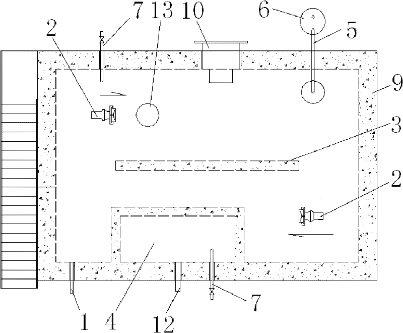
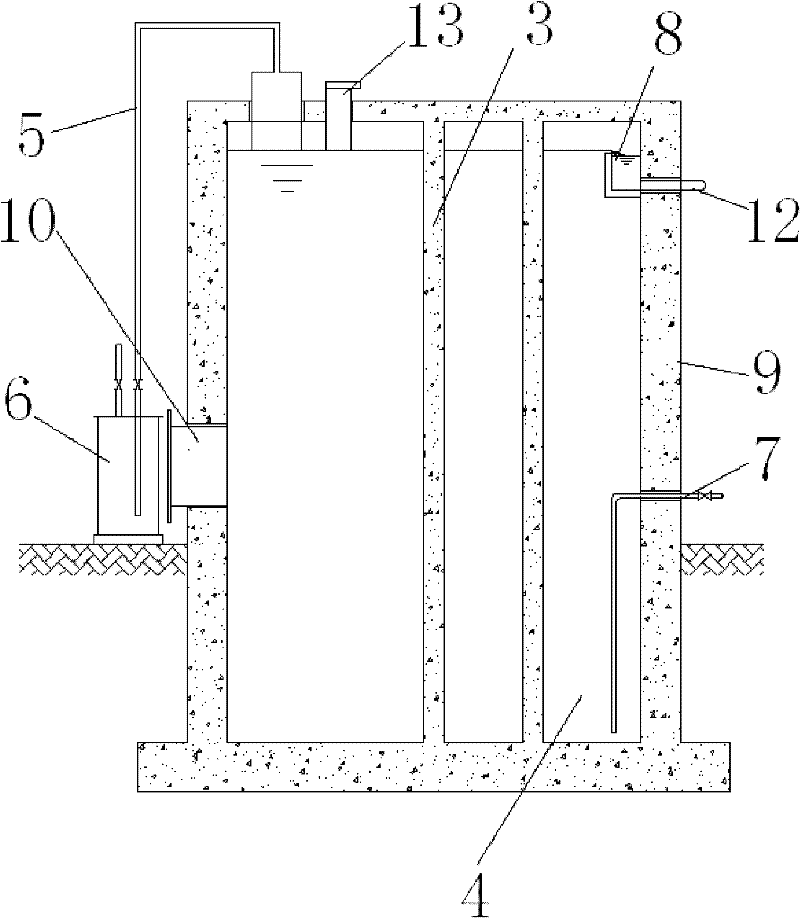
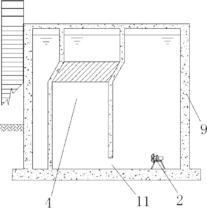
[0026] Such as Figure 1 ~ Figure 3 An internal circulation anaerobic reactor is shown, which includes a pool body 9, a biogas collection pipe 5 connected to the pool body 9, and a water seal tank 6. The internal circulation anaerobic reactor also includes a water inlet pipe 1 and a slanted plate sedimentation tank 4. The middle part of the pool body 9 is provided with a partition wall 3, and the two opposite corners of the pool body 9 are respectively equipped with submersible propellers 2 that push the mixed water in the pool to flow around the partition wall 3, and the inclined plate sedimentation tank 4 is arranged on the pool body 9 On the inner side, the lower end of the inclined plate sedimentation tank 4 is provided with an opening 11 communicating with the inclined plate sedimentation tank 4 and the tank body 9 . The inclined plate settling tank 4 is a closed type, and only the opening 11 is left. The submersible thruster 2 pushes the mixed water body mixed with mudd...


PUM


Abstract

The invention discloses an internal circulation anaerobic reactor. The anaerobic reactor comprises a tank body, a biogas collection pipe internally communicated with the tank body and a water-sealed tank and also comprises a water inlet pipe and an inclined plate setting tank, wherein the middle of the tank body is provided with an isolation wall; two inner opposite corners of the tank body are separately provided with submerged propellers which are used to push the mixed water body in the tank to flow along the isolation wall; the inclined plate setting tank is arranged on one side of the inside of the tank; and the lower end of the inclined plate setting tank is provided with an opening communicated with the inclined plate setting tank and the tank body. By adopting the structure, the internal circulation anaerobic reactor has the following advantages: 1) water circulation can be realized in the tank body, the flow rate is stable on each section which is perpendicular to the flowingdirection in a steady state; 2) on each section of the reactor, the concentration of material can not change with time, the loss of sludge can be reduced; 3) fluid particles can not be mixed in the flowing direction of fluid, the backmixing phenomenon does not exist, all the fluid particles have the same residence time; 4) mud and water can be fully mixed; and 5) the impact resistance can be increased.

Description

technical field [0001] The invention relates to the technical field of water treatment, in particular to an internal circulation anaerobic reactor. Background technique [0002] The booster anaerobic reactor is mainly used for sewage treatment and is a kind of anaerobic reactor. The traditional upflow anaerobic sludge bed (UASB) consists of three parts: the reaction zone, the gas-liquid-solid three-phase separator (including the sedimentation zone) and the gas chamber. A large amount of anaerobic sludge remains in the bottom reaction zone, and the sludge with good sedimentation and coagulation properties forms a sludge layer in the lower part. The sewage to be treated flows from the bottom of the anaerobic sludge bed and is mixed and contacted with the sludge in the sludge layer. The microorganisms in the sludge decompose the organic matter in the sewage and convert it into biogas. The biogas is continuously released in the form of micro-bubbles, and the micro-bubbles are ...

Claims


Application Information

Patent Timeline
Patent Type & Authority Patents(China)
IPC IPC(8): C12M1/02C02F3/28
CPCC12M23/34Y02E50/343C12M41/00C12M23/36C12M21/04Y02E50/30
Inventor 杨志慧梁斌斌冯慧敏李争国赵小宝
Owner 芜湖慧安水处理科技有限公司
Why Eureka
Try Eureka