Coaxial dual-electron beam electron gun

A technology of dual electron beams and electron guns, applied in the field of electron guns, can solve problems such as difficult to improve performance, cannot be set arbitrarily, and difficult to miniaturize devices, so as to achieve the effect of improving performance

Active Publication Date: 2011-08-17
成都华聚科技有限公司
View PDF3 Cites 7 Cited by
  • Summary
  • Abstract
  • Description
  • Claims
  • Application Information

AI Technical Summary

Problems solved by technology

In this patented technology, since the inner conductor (inner anode) is located in the cathode sleeve, and the cathode sleeve is located in the outer conductor (outer anode), in order to avoid high-voltage breakdown between the inner and outer conductors (outer anode) and the cathode, the inner and outer conductors ( anode) and the minimum distance between the cathode casing is limited
Therefore, the radius of the electron beam emission ring of the cathode sleeve and the inner diameter of the outer conductor (outer anode) in this type of electron gun are limited and cannot be set arbitrarily; especially the working potential difference between the in

Method used


Image

  • Coaxial dual-electron beam electron gun
  • Coaxial dual-electron beam electron gun
  • Coaxial dual-electron beam electron gun

Examples


Embodiment 1

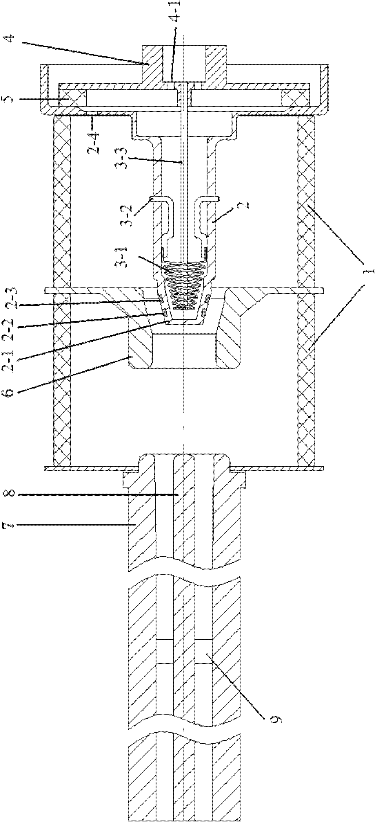
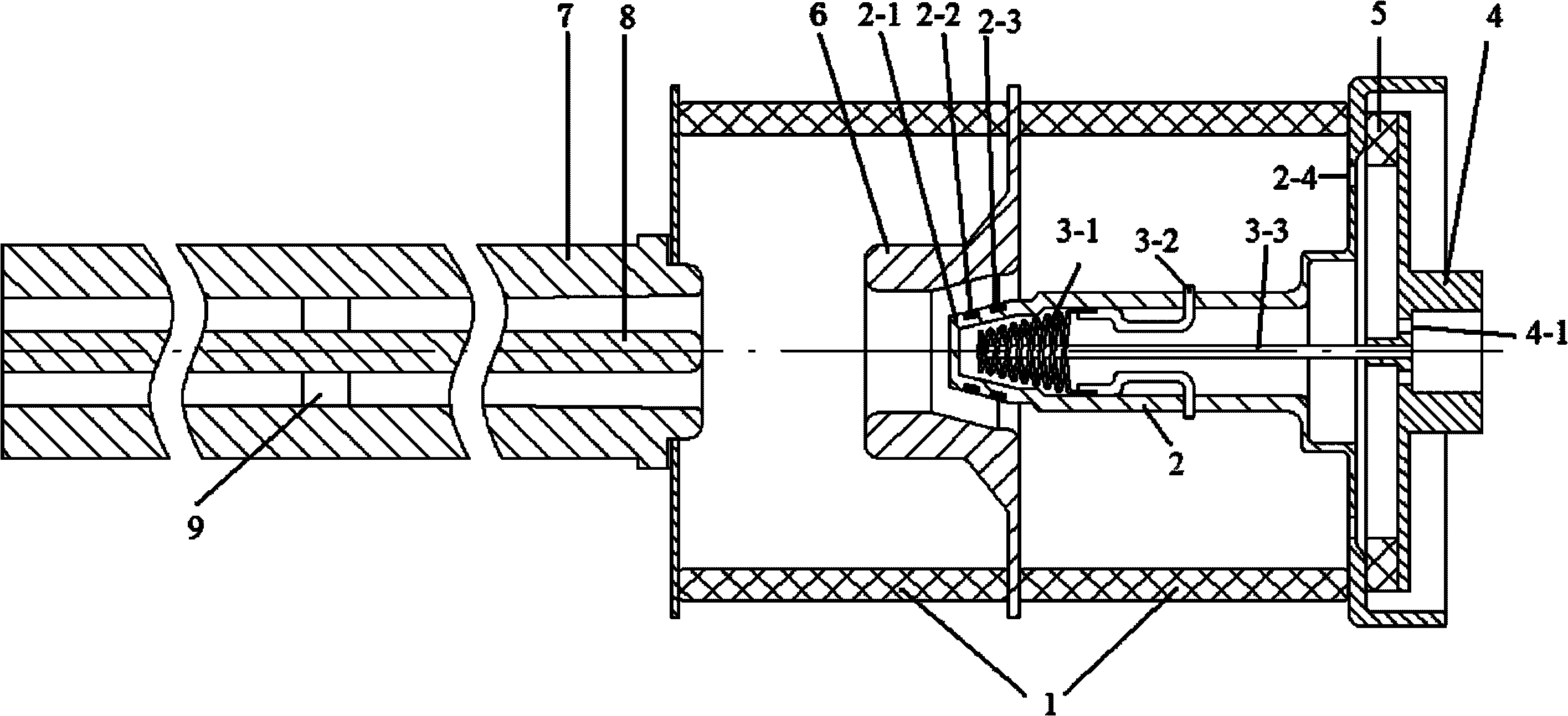
[0012] Take the coaxial double electron beam electron gun used in conjunction with the coaxial resonant cavity double electron beam gyrotron used for heating plasma as an example: the electron gun barrel 1 has an axial length of 250mm, and the inner and outer diameters are Φ120mm and Φ150mm respectively. for 99 # Ceramics, two ports are metallized, the upper and lower sections of the cylinder body 1 in this embodiment are sealed into a whole with the chassis of the control anode 6; the axial length of the cathode sleeve 2 is 200mm, and the outer diameter of the main (sleeve) body part of the cathode sleeve is Φ54mm, wall thickness 5mm, front conical cathode head 2-1 length 25mm, inclination angle 15 degrees, cathode sleeve 2 is sealed with the rear end surface of electron gun barrel 1 and insulating ring 5 respectively through its fixing seat with vent hole 2-4 Fixed; the diameters of the upper and lower ring openings of the electron beam emitting ring 2-2 are Φ47.8mm and Φ48....

Embodiment 2

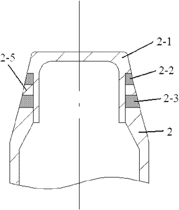
[0015] In this embodiment, the cathode head 2-1 adopts a combined cathode head as an example: the electron beam emission rings 2-2 and 2-3 all adopt ring cone emission rings, and the diameters of the upper and lower ring openings of the electron beam emission ring 2-2 They are Φ47.8mm and Φ48.2mm respectively, the diameters of the upper and lower ring openings of the electron beam emitting ring 2-3 are Φ51.9mm and Φ52.1mm respectively, the inner diameters are both Φ40mm, and the inclination angle of the outer cone annulus is 15 degrees; the isolation ring 2- 5 is placed between the ring cone launch rings 2-2 and 2-3, the inclination angle of the outer cone ring surface is still 15 degrees, and the inner diameter is Φ40mm. In this embodiment, the outer diameter of the joint between the end of the cathode head 2-1 and the ring cone emission rings 2-2, 2-3, the isolation ring 2-5, and the main body of the cathode sleeve is Φ40mm, and it is welded with the main body of the cathode ...


PUM


Abstract

The invention belongs to a coaxial dual-electron beam electron gun assorted with a gyrotron (an oscillator and an amplifier), which comprises an electron gun barrel body, a base, a cathode sleeve with an electric heating wire and two electron beam emitting rings, internal and external anodes and a control anode. In the coaxial dual-electron beam electron gun, the internal and external anodes and the cathode sleeve are arranged oppositely and coaxially, the internal anode and the external anode are still arranged in an overlapping (telescopic) way, and the control anode is also arranged between the internal and external anodes and a cathode head to regulate the current of an electron beam and the rotation speed and axial speed of the electron beam in the gyrotron. Therefore, the invention has the characteristics that: output power can be regulated quickly, work efficiency of the gyrotron also can be regulated arbitrarily within the range of the peak efficiency of the gyrotron, the performance of the coaxial dual-electron beam electron gun and the application range of the gyrotron assorted with the electron gun are improved effectively, breakdown between the internal and external anodes and the cathode sleeve and between the control anode and the cathode sleeve is prevented, the coaxial dual-electron beam electron gun is favorable for the miniaturization of devices, and the like.

Description

technical field [0001] The invention belongs to the electron gun matched with a gyrotron (oscillator, amplifier) ​​in the technical field of high-power microwave, millimeter wave and submillimeter wave, and in particular relates to a coaxial double electron beam electron gun. Background technique [0002] As a new type of high-power microwave, millimeter wave, and submillimeter wave devices, the gyrotron has developed rapidly since its inception. A series of gyrotron devices have been successfully developed, and its wave band has reached the millimeter wave and submillimeter wave bands. The power is as high as several megawatts. The average power has reached hundreds of kilowatts. In the millimeter wave and submillimeter wave bands, this is unmatched by ordinary microwave tubes, and has great application prospects in microwave, millimeter wave, submillimeter wave radar, communication and other fields; in the sintering of high-performance precision ceramics, nuclear magnetic ...

Claims


Application Information

Patent Timeline
IPC IPC(8): H01J23/06
Inventor 傅文杰鄢扬刘盛纲
Owner 成都华聚科技有限公司
Why Eureka
Try Eureka