Single-phase non-isolation type photovoltaic grid-connected inverter and control method

A non-isolation and inverter technology, applied in photovoltaic power generation, single-network parallel feed arrangement, AC power input conversion to DC power output, etc., can solve the problems of ineffective suppression of common-mode current and improve power conversion efficiency , The effect of reducing the loss of the switching tube and reducing the common mode voltage

Inactive Publication Date: 2011-08-17
TBEA SUNOASIS +1
View PDF4 Cites 17 Cited by
  • Summary
  • Abstract
  • Description
  • Claims
  • Application Information

AI Technical Summary

Problems solved by technology

[0006] The technical problem to be solved by the present invention is to provide a single-phase non-isolated photovoltaic grid-connected inverter and a control method for the deficiency that the single-phase non-isolate

Method used


Image

  • Single-phase non-isolation type photovoltaic grid-connected inverter and control method
  • Single-phase non-isolation type photovoltaic grid-connected inverter and control method
  • Single-phase non-isolation type photovoltaic grid-connected inverter and control method

Examples


Embodiment 2

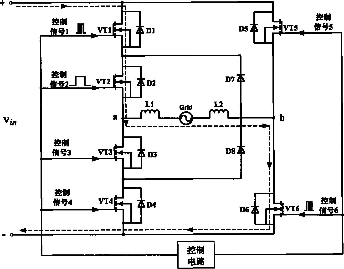
[0050] The control mode and control signal timing diagram in embodiment 2 are also the same as in embodiment 1. In the positive half cycle of the grid voltage, the switch tube VT2 is normally on and works at the power frequency frequency; the switch tubes VT1 and VT6 work synchronously at the high frequency frequency; The switch tubes VT3, VT4 and VT5 are cut off. When the switching tubes VT1, VT6 working at high frequency and the switching tube VT2 working at power frequency are turned on, the current in the circuit flows through the switching tubes VT1, VT2, L1, L2, and VT6 in sequence. The path of the freewheeling circuit in the positive half cycle of the grid voltage is: in the positive half cycle of the grid voltage, when the switching tubes VT1 and VT6 working at high frequency are cut off, and the switching tube VT2 working at power frequency is turned on, the current in the circuit flows sequentially. A freewheeling circuit is formed through VT2, L1, L2, D7, and VT2. ...

Embodiment 3

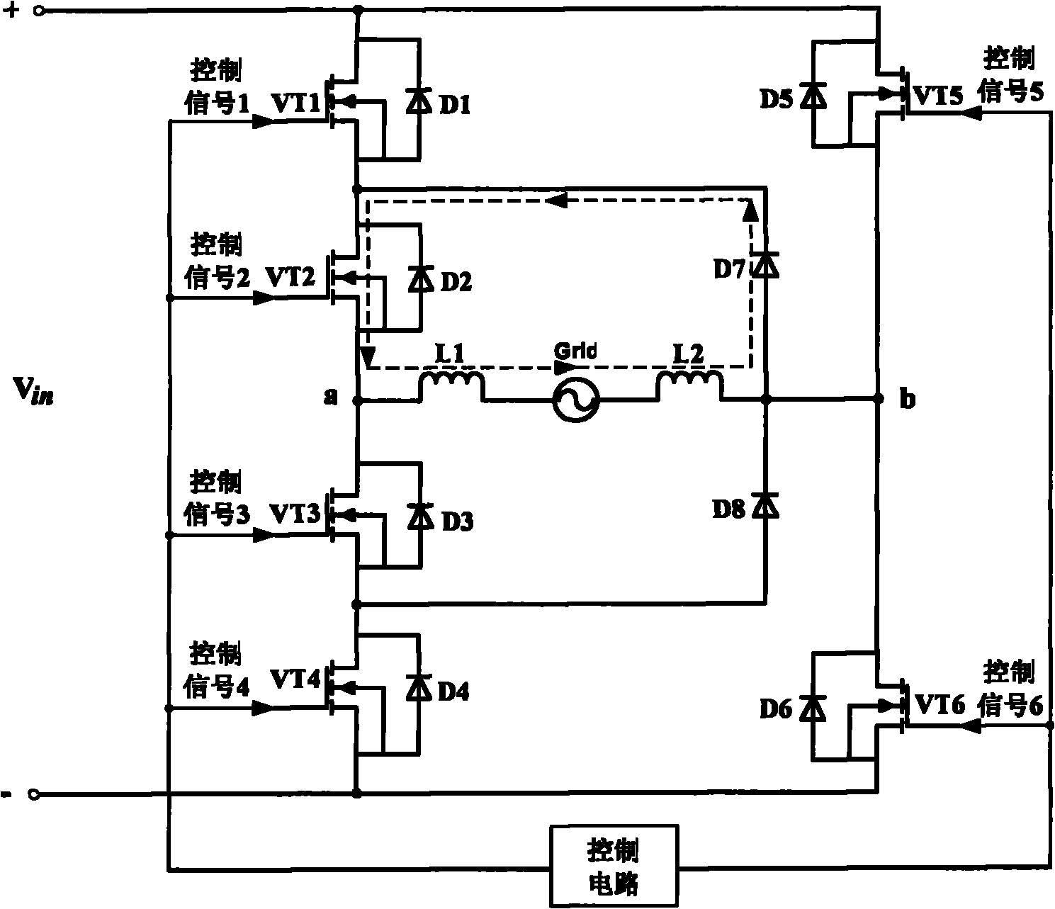
[0053] The control mode and control signal timing diagram in embodiment 3 are also the same as in embodiment 1. In the positive half cycle of the grid voltage, the switch tube VT2 is normally on and works at the power frequency frequency; the switch tubes VT1 and VT6 work synchronously at the high frequency frequency; The switch tubes VT3, VT4 and VT5 are cut off. When the switching tubes VT1, VT6 working at high frequency and the switching tube VT2 working at power frequency are turned on, the current in the circuit flows through the switching tubes VT6, L1, L2, VT2, VT1 in sequence. The path of the freewheeling circuit in the positive half cycle of the grid voltage is: in the positive half cycle of the grid voltage, when the switching tubes VT1 and VT6 working at high frequency are cut off, and the switching tube VT2 working at power frequency is turned on, the current in the circuit flows sequentially. A freewheeling circuit is formed through VT2, D7, L1, L2, and VT2.

[0...


PUM


Abstract

The invention discloses a single-phase non-isolation type photovoltaic grid-connected inverter and a control method. The photovoltaic grid-connected inverter comprises a full-bridge circuit, a control circuit and a fly-wheel diode, wherein the control circuit is used for controlling conduction and cut-off of all switching tubes in the full-bridge circuit so as to convert direct current voltage generated by a photovoltaic array of the full-bridge circuit to sine wave voltage required for grid connection; and the fly-wheel diode is used for providing a fly-wheel loop so as to thoroughly disconnect the input side from a power grid. The photovoltaic grid-connected inverter can effectively inhibit common-mode current (namely drain current) of the single-phase non-isolation type photovoltaic grid-connected inverter and improve the electrical energy conversion efficiency of the inverter.

Description

technical field [0001] The invention belongs to the technical field of active inverters, and relates to a photovoltaic grid-connected inverter, in particular to a single-phase non-isolated photovoltaic grid-connected inverter and a control method. Background technique [0002] The photovoltaic grid-connected system refers to a system that converts the direct current generated by the solar photovoltaic array into alternating current with the same amplitude, frequency and phase as the grid voltage through the grid-connected inverter, and realizes the connection with the grid. Isolated photovoltaic grid-connected inverters with power frequency or high-frequency transformers are often used in photovoltaic grid-connected systems, which ensures electrical isolation between the grid and the photovoltaic system, thereby providing personal protection and avoiding contact between the photovoltaic system and the ground. common mode current. However, if a power frequency transformer is...

Claims


Application Information

Patent Timeline
IPC IPC(8): H02J3/38H02M7/497H02M7/5387H02M1/32
CPCH02M2001/123H02M7/487Y02E10/56Y02E10/563H02M7/5388H02M1/123
Inventor 刘伟增刘小刚张新涛吴军利梁欢迎
Owner TBEA SUNOASIS
Why Eureka
Try Eureka