
Multi-channel isolated high-speed intelligent transmitting-receiving device and method for power electronic system

A transceiver device, power electronics technology, applied in the direction of output power conversion device, transmission system, synchronization device, etc., can solve the problem of lack of independent priority judgment and error correction ability, increased calculation amount of lower-layer control unit, and complicated wiring and cost increase, etc., to reduce the signal interference path, improve accuracy and reliability, and simplify the connection

Inactive Publication Date: 2013-11-06
ZHEJIANG UNIV
View PDF3 Cites 0 Cited by
  • Summary
  • Abstract
  • Description
  • Claims
  • Application Information

AI Technical Summary

Problems solved by technology

If there is an error in sampling, it will greatly affect the system performance, and may even lead to the paralysis of the entire system
[0003] At present, traditional sensors are mostly simple passive sampling and signal transmission, without independent priority judgment and error correction capabilities, which will increase the amount of calculation of the lower control unit and slow down the system response speed
Moreover, traditional sensors only transmit one signal. For three-phase or multi-phase applications, multiple voltage and current signals need to be monitored at the same time, which will significantly increase the complexity and cost of wiring.
Judging from the current development, the main control unit of the complex power electronic system generally adopts the digital control method. When the traditional sensor is used, an analog-to-digital conversion is performed at the control end. This process is prone to errors or interference.

Method used


Image

  • Multi-channel isolated high-speed intelligent transmitting-receiving device and method for power electronic system
  • Multi-channel isolated high-speed intelligent transmitting-receiving device and method for power electronic system
  • Multi-channel isolated high-speed intelligent transmitting-receiving device and method for power electronic system

Examples


Embodiment Construction

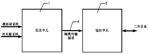
[0039]In the multi-channel isolated high-speed intelligent transceiver device of the present invention, the isolated transmission medium 4 can be optical fiber isolation, radio frequency wireless signal isolation, a combination of multi-core cable and optocoupler isolation, or a combination of multi-core cable and transformer isolation. Signals exist in different forms in different isolation transmission media, for example, laser is used in optical fiber for transmission, and magnetic field alternating signal is used in transformer isolation. The invention thoroughly solves the problem that the signal transmission wiring in the power electronic system is easily subjected to electromagnetic interference and the like, and improves the accuracy and reliability of the system.

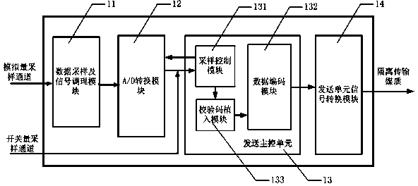
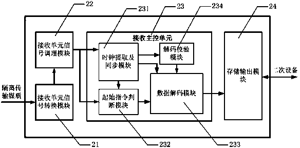
[0040] The modules in the sending main control unit 13 and the receiving main control unit 23 of the present invention exist in the form of programmable modules, and their definitions include data conversion...


PUM


Abstract

The invention discloses a multi-channel isolated high-speed intelligent transmitting-receiving device and method for a power electronic system. The device comprises transmitting units, receiving units and isolated transmission mediums. Each transmitting unit comprises a data sampling and signal conditioning module, an A / D (Analog / Digital) conversion module, a transmitting main control unit and a transmitting unit signal conversion module; each receiving unit comprises a receiving unit signal conversion module, a receiving unit signal conditioning module, a receiving main control unit and a memory output module. The device can perform digital coding on multi-channel analog sampling and switch sampling, and transmits through the isolated transmission mediums; each receiving unit can be connected with a plurality of the transmitting units for simultaneously decoding. The multi-channel isolated high-speed intelligent transmitting-receiving device has the advantages of prominent high-reliable electrical isolation performance, instantaneity and intelligent performance.

Description

technical field [0001] The invention relates to a multi-channel isolated high-speed intelligent transceiver device and method for power electronic systems, and is especially suitable for sampling design of complex medium and large power electronic systems. Background technique [0002] At present, a development trend of power electronic devices is system complexity and high power. The main power devices of power electronic devices generate high current and voltage change rates during the switching process, which generate electromagnetic waves through parasitic capacitance and inductance in the circuit. Noise can easily interfere with the sampling line and affect the sampling accuracy. Most of the control units of traditional power converters are directly connected to the sampling unit through metal cables, and the electromagnetic environment can easily affect the signal transmission in the cables. The digital signal processor reacts by sampling the signal and transmits it t...

Claims


Application Information

Patent Timeline
Patent Type & Authority Patents(China)
IPC IPC(8): H04L7/033H04L1/00H02M1/44
Inventor 吕征宇靳晓光张德华杭丽君
Owner ZHEJIANG UNIV
Learn More