Micro-electrode array chip before retina in field of artificial vision

A micro-electrode array and artificial vision technology, applied in ophthalmology treatment, etc., can solve problems such as poor closure of sclera incision, inability to stimulate other areas of the retina, etc., to prevent sympathetic ophthalmia, reduce the difficulty of welding, and prevent choroidal hemorrhage Effect

Inactive Publication Date: 2011-08-24
PEOPLES HOSPITAL PEKING UNIV
View PDF4 Cites 9 Cited by
  • Summary
  • Abstract
  • Description
  • Claims
  • Application Information

AI Technical Summary

Problems solved by technology

[0005] 1. Fixing the microelectrode array on the anterior surface of the retina requires the use of titanium nails to punch holes in the retina, which increases the risk of rhegmatogenous retinal detachment;
[0006] 2. Titanium nails are placed on the posterior pole of the retina, where the blood supply of the choroid is rich, and it is easy to cause choroidal hemorrhage or even choroidal hemorrhage;
[0007] 3. Due to damage to the choroid (a part of the uvea), it is easy to induce uveitis, and even cause sympathetic ophthalmia in the fellow eye;
[0008] 4. Titanium nails are designed with barbs, which are not easy to take out after being nailed into the eyeball wall. If the microelectrode array needs to be taken out or replaced after a period of use, it will be very difficult;
[0009] 5. The microelectrode array can only stimulate the macular area of ​​the retina, but cannot stimulate other areas of the retina, that is, the patient can only restore part of the central vision, but the peripheral vision cannot be restored
[0010] 6. After the microelectrode array elicits the eyeball, the closure of the scleral incision is poor, and it is easy to form incision leakage

Method used


Image

  • Micro-electrode array chip before retina in field of artificial vision
  • Micro-electrode array chip before retina in field of artificial vision
  • Micro-electrode array chip before retina in field of artificial vision

Examples


Embodiment Construction

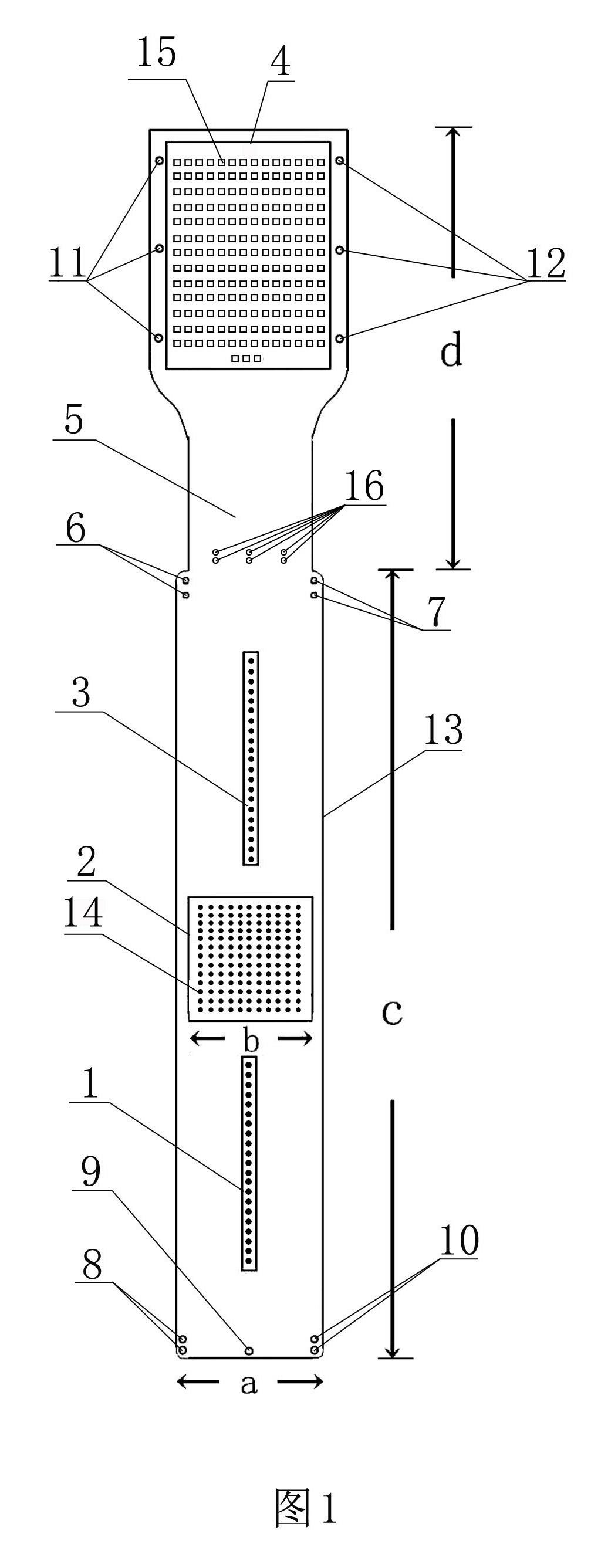
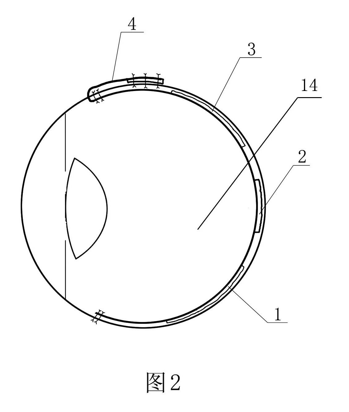
[0031] Examples see figure 1 , figure 2 As shown, a preretinal microelectrode array chip used in the field of artificial vision includes a chip substrate 13, wires embedded in the chip substrate 13, and microelectrodes that protrude from the surface of the substrate and form an array. It is characterized in that: The lower end edge of the chip substrate 13 is provided with at least two reserved holes 8, 9, and 10 for lower sutures, and the chip substrate 13 is sequentially arranged with a micro-electrode arrangement lower area 1, a micro-electrode arrangement middle area 2, and a micro-electrode arrangement area. Electrode arrangement upper area 3, base narrowing area 5 and base widening area 4, said chip base 13 has at least three sets of two reserved holes 16 for scleral incision sutures respectively at the lower end adjacent to base narrowing area 5, two of which are At least two upper suture reserved holes 6, 7 are respectively opened on the edge, and outer suture reser...


PUM


Abstract

The invention discloses a micro-electrode array chip before retina in the field of artificial vision. The micro-electrode array chip comprises a chip substrate, a lead buried in the chip substrate and micro-electrodes protruding the surface of the substrate and forming an array. The edge of the lower end of the chip substrate is provided with at least two lower suture line preformed holes; a micro-electrode arrangement lower area, a micro-electrode arrangement middle area, a micro-electrode arrangement upper area, a substrate reduction area and a substrate expansion area are sequentially arranged on the chip substrate from bottom to top; the substrate expansion area contains contacts corresponding to the electrode arrangement areas, and are connected with the micro-electrodes through the lead buried in the chip substrate; the chip substrate close to the lower end of the substrate reduction area is provided with at least three groups of two sclera cut suture line preformed holes, and two edges are respectively provided with at least two upper suture line preformed holes; and two sides of the substrate expansion area are provided with eye external suture line preformed holes. The micro-electrode array chip can stimulate retinal ganlion cells of the blind to recover partial vision of the blind, and avoids rhegmatogenous retinal detachment, choroidal hemorrhage and sympathetic ophthalmia caused by iatrogenic retinal breaks.

Description

technical field [0001] The invention relates to an ophthalmic medical device, in particular to a preretinal microelectrode array chip used in the field of artificial vision. Background technique [0002] The visual system is the most important source of information for human beings to understand and transform the objective world. The human visual system is composed of the refractive interstitium of the eye and the visual nervous system, forming a complete process of optical signal propagation, photoelectric conversion, and electrical signal processing and transmission, and finally perceived by the visual center combined with people's life experience. Although today's medical methods have effective treatments for many blinding eye diseases such as trachoma, cataract, glaucoma, etc., they are still not very effective for retinal diseases such as retinitis pigmentosa (RP) where the outer retina (photoreceptors) is destroyed. therapy. As far as RP is concerned, its incidence r...

Claims


Application Information

Patent Timeline
Patent Type & Authority Applications(China)
IPC IPC(8): A61F9/08
Inventor 王凯黎晓新
Owner PEOPLES HOSPITAL PEKING UNIV
Why Eureka
Try Eureka