
Preparation method of ZnS/Si nuclear-shell nanowires or nanobelts and polycrystal Si tubes

A nanobelt and nanowire technology, which is applied in the field of ZnS/Si core-shell nanowire or nanobelt and polycrystalline Si tube preparation, can solve the problem that it is difficult to control the shape and diameter of silicon-based semiconductor nanomaterials, and achieve low cost. , Simple operation, good controllability

Inactive Publication Date: 2011-08-24
TECHNICAL INST OF PHYSICS & CHEMISTRY - CHINESE ACAD OF SCI
View PDF0 Cites 5 Cited by
  • Summary
  • Abstract
  • Description
  • Claims
  • Application Information

AI Technical Summary

Problems solved by technology

Although the above methods can already prepare heterojunctions such as Si / Ge, Si / SiGe, Si / SiO2, Si / Sn, etc., it is difficult to control the morphology of the resulting silicon-based semiconductor nanomaterials. and diameter

Method used


Image

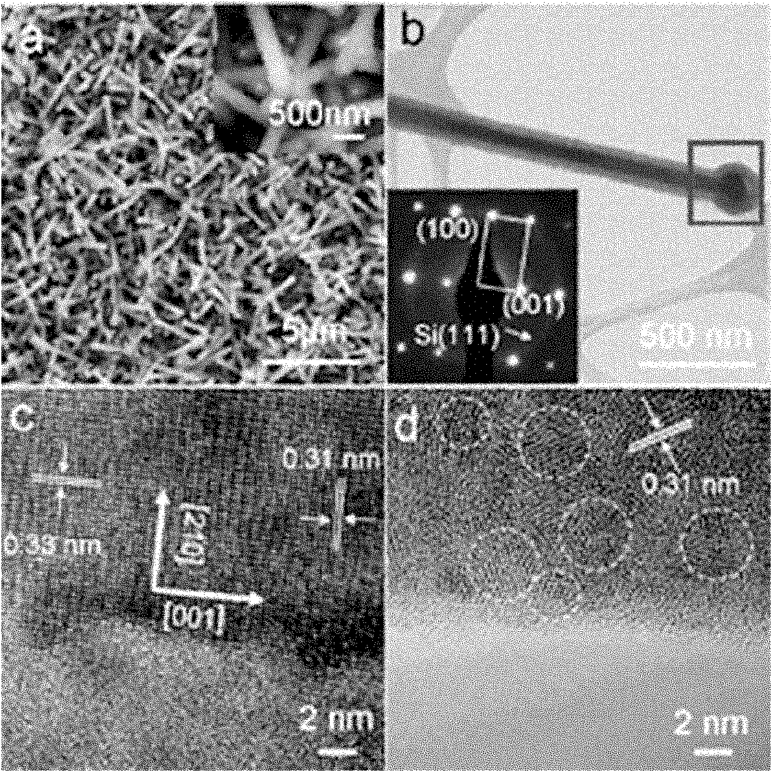
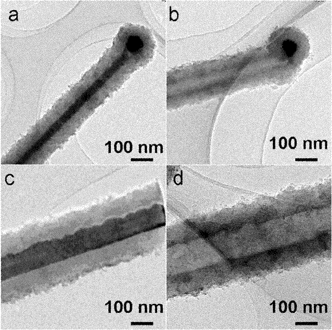
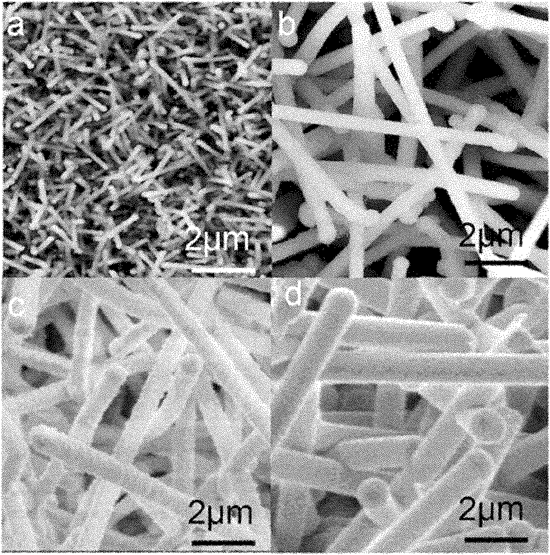
  • Preparation method of ZnS/Si nuclear-shell nanowires or nanobelts and polycrystal Si tubes
  • Preparation method of ZnS/Si nuclear-shell nanowires or nanobelts and polycrystal Si tubes
  • Preparation method of ZnS/Si nuclear-shell nanowires or nanobelts and polycrystal Si tubes

Examples


Embodiment 1

[0027] (1) Preparation of ZnS template

[0028] First, the alumina tube was installed in a vacuum tube furnace as a heating chamber, 2g of ZnS powder (Alfa Aldrich, 99.99%) was placed in the middle of the alumina tube as an evaporation source, and a silicon wafer with a 5nm gold film evaporated was placed in the Downstream in the direction of airflow in the pipe.

[0029] Secondly, seal the whole system and pump the pressure inside the pipe to 6×10 -2 Pa, filled with 5% H 2 high-purity Ar gas at a rate of 25 cubic centimeters per minute, and keep the pressure in the tube at 4×10 4 Pa. The middle part of the tube, where the ZnS powder is located, is heated to 1050°C at a rate of 20°C per minute. At this time, the substrate region has a temperature gradient of 900°C to 400°C along the gas flow direction, and the temperature gradient is maintained for about 4 hours.

[0030] Finally, the heating is stopped, the tube is cooled to room temperature, ZnS nanowires are formed in t...

Embodiment 2

[0038] (1) Preparation of ZnS template

[0039] First, the alumina tube was installed in a vacuum tube furnace as a heating chamber, 2g of ZnS powder (Alfa Aldrich, 99.99%) was placed in the middle of the alumina tube as an evaporation source, and a silicon wafer with a 5nm gold film evaporated was placed in the Downstream in the direction of airflow in the pipe.

[0040] Secondly, seal the whole system and pump the pressure inside the pipe to 6×10 -2 Pa, filled with 5% H 2 high-purity Ar gas at a rate of 50 cubic centimeters per minute, and keep the pressure in the tube at 1×10 4 Pa. The middle part of the tube, where the ZnS powder is located, is heated to 1100°C at a rate of 50°C per minute. At this time, the substrate region has a temperature gradient of 900°C to 400°C along the gas flow direction, and the temperature gradient is maintained for about 2 hours.

[0041] Finally, the heating is stopped, the tube is cooled to room temperature, ZnS nanowires are formed in t...


PUM


Abstract

The invention discloses a preparation method of ZnS / Si nuclear-shell nanowires or nanobelts and polycrystal Si tubes. The preparation method comprises the following steps: carrying out two-step thermal evaporation in a vacuum tubular furnace, synthesizing the ZnS / Si nuclear-shell nanowires or nanobelts with different diameters by taking ZnS with different shapes as templates and controlling the growth time of Si, and processing with diluted hydrochloric acid to obtain the polycrystal Si tubes with multiple shapes and different diameters. The preparation method is simple to operate, has good controllability, and is suitable to large-scale production of the ZnS / Si nuclear-shell nanowires or nanobelts and polycrystal Si tubes, with multiple shapes and the different diameters. A one-dimensional nano material obtained with the method in the invention has a wide application prospect in the aspects of silicon-substrate integrated circuits, nano optical devices, nano sensors and the like.

Description

technical field [0001] The invention relates to a method for preparing ZnS / Si core-shell nanowires or nanobelts and polycrystalline Si tubes, in particular to a preparation method for ZnS / Si core-shell nanowires or nanobelts and polycrystalline Si tubes with controllable morphology and diameter method. The invention belongs to the field of controllable synthesis of Si-based semiconductor nanometer materials. Background technique [0002] Since silicon is an important semiconductor material, and the one-dimensional nano-heterojunction has excellent photoelectric properties, the silicon-based one-dimensional nano-heterojunction has great application potential in semiconductor devices. At present, silicon-based one-dimensional nano-semiconductor heterojunctions can be prepared by various methods, such as chemical vapor deposition, pulsed laser deposition, and solution growth. Although the above method can already prepare Si / Ge, Si / SiGe, Si / SiO 2 , Si / Sn and other heterojunct...

Claims


Application Information

Patent Timeline
IPC IPC(8): C30B29/46C30B29/62C30B29/66C30B33/10
Inventor 孟祥敏陈雪
Owner TECHNICAL INST OF PHYSICS & CHEMISTRY - CHINESE ACAD OF SCI
Learn More