Light adjusting film electrode manufacture method

A light-adjusting film and electrode manufacturing technology, which is applied in optics, nonlinear optics, instruments, etc., can solve the problems of copper foil contact failure, affecting electrical contact, liquid crystal film controllability and display effect deterioration, etc.

Active Publication Date: 2011-08-24
SHANGHAI LONGSHENG PHOTOELECTRIC NEW MATERIAL CO LTD
View PDF5 Cites 7 Cited by
  • Summary
  • Abstract
  • Description
  • Claims
  • Application Information

AI Technical Summary

Problems solved by technology

[0004] However, because the above-mentioned switchable glass needs to change the transparency of the glass freely by electric current, it needs to be connected with electrodes for external power conduction. Generally, manufacturers use cutting methods to cut the two sides of the switchable glass from the top and bottom respectively, and the single The layer of glass and conductive film is cut off, and then the copper foil contact and the side wall of the conductive film are glued together through the adhesive material, and a conductive wire is welded on the copper foil contact; since the conductive wire is directly welded to the copper foil contact, When soldering, a high temperature (about 250°C to 500°C) will be generated. Since the solder point is directly on the conductive film, the high temperature will be transmitted to the liquid crystal film, which will deteriorate the controllability and display effect of the liquid crystal film. Furthermore, the copper foil The contact is flat and hard, which will not only cause unevenness, so that the copper foil contact cannot be firmly bonded to the conductive film, and the gap will affect the electrical contact, and the copper foil contact will easily fall off. question

Method used


Image

  • Light adjusting film electrode manufacture method
  • Light adjusting film electrode manufacture method
  • Light adjusting film electrode manufacture method

Examples


Embodiment Construction

[0034] The following will be described in detail in conjunction with the accompanying drawings and preferred embodiments for complete understanding.

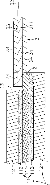
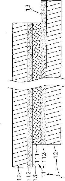
[0035] see figure 1 As shown, it is a side view of a preferred embodiment of the present invention. It can be clearly seen from the figure that it includes a dimming film 1, a conductive glue 2 and an electrode module 3, wherein:

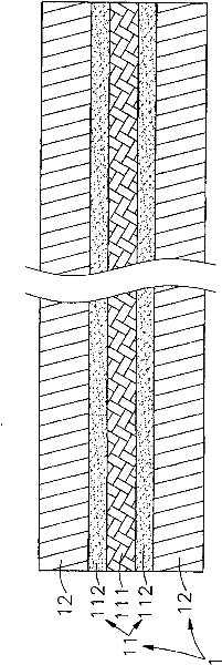
[0036] The dimming film 1 is composed of a dimming liquid crystal layer 11 and a pressure sensitive adhesive 12 (Pressure Sensitive Adhesive, PSA) on both sides thereof. The liquid crystal layer 111 produced by the mixing of liquid crystals, its high-molecular adhesive polymer can be polyisocyanate cross-linked hydroxyl group, hydroxyl polyacrylate or acrylic resin, and a conductive film 112 is respectively provided on the two sides of the liquid crystal layer 111. The film 112 can be polyethylene terephthalate sputtered with a layer of indium tin oxide (Indium Tin Oxide, ITO), then the outer surface...


PUM


Abstract

The invention relates to a light adjusting film electrode manufacture method. The light adjusting film comprises light adjusting liquid crystal layers arranged on both side surfaces of a liquid crystal layer and respectively provided with a conductive film, wherein pressure-sensitive adhesives are respectively applied on the outer side of the two conductive films relative to the liquid crystal layer. The light adjusting film electrode manufacture method comprises the following steps: respectively cutting both sides of the light adjusting film from the upper surface and the lower surface; sequentially removing one layer of the pressure-sensitive adhesive, the conductive film and the liquid crystal layer from outside to inside to form a connection groove; applying a conductive adhesive on the surface of the conductive film on the inner side of the connection groove; arranging a reticular conductor on the conductive film, wherein the exposed part of the reticular conductor extends out of the light adjusting film; curing the conductive adhesive by an overheating furnace; forming solder joints on the surface of the exposed part of the reticular conductor by welding to connect conducting wires; and embedding the solder of the solder joints in the grid structure of the reticular conductor to substantially and effectively connect the conductive film and the reticular conductor through the conductive adhesive firmly. Further, the welding heat is prevented from being conducted to the liquid crystal layer and the conductive film so as not to destroy the liquid crystal layer and the conductive film, and the voltage and the current can be uniformly and effectively conducted to the conductive film through the reticular conductor to improve the response and the efficiency of the light adjusting film.

Description

technical field [0001] The invention provides a method for manufacturing a dimming film electrode, in particular, it is directed to sequentially arrange conductive glue and a mesh conductor on the conductive film, and then let the conductive glue cure through a heating furnace to firmly combine the conductive film and the mesh conductor. The exposed part of the mesh conductor on the outside of the dimming film is welded with conductive wires, which not only allows the solder to sink into the mesh conductor to form a stable bond, but also prevents the high temperature of welding from directly affecting the liquid crystal layer and the conductive film. Background technique [0002] Press, in the early days, in order to make doors, windows or partition glass concealed, and to isolate factors from sunlight, curtains, Low-E glass or thermal insulation paper were installed on the outside of the glass. Taking thermal insulation paper as an example, because Thermal insulation paper ...

Claims


Application Information

Patent Timeline
Patent Type & Authority Applications(China)
IPC IPC(8): G02F1/133G02F1/1334
Inventor 邱达成
Owner SHANGHAI LONGSHENG PHOTOELECTRIC NEW MATERIAL CO LTD
Why Eureka
Try Eureka