Natural gas dehydration method using pre-nucleating supersonic vortex tube

A supersonic, vortex tube technology, applied in separation methods, chemical instruments and methods, gas fuels, etc., can solve the problems of difficult to grasp nucleation particle size and nucleation number, blocked pipelines, difficult nucleation, etc., and achieves optimization. Gas-liquid separation performance, improving condensation efficiency, good application prospects

Active Publication Date: 2011-08-31
PETROCHINA CO LTD
View PDF15 Cites 6 Cited by
  • Summary
  • Abstract
  • Description
  • Claims
  • Application Information

AI Technical Summary

Problems solved by technology

However, in the supersonic state, it is difficult to achieve good nucleation in such a short time and space, and it is also difficult to control the nucleation particle size and nucleation number.
This uncontrolled natural nucleation process will lead to inefficient gas-liquid separation in supersonic vortex tubes, lower dew point drop, and higher pressure drop requirements
In addition, when the uncontrolled natural nucleation process is applied to occasions where solids (such as natural gas hydrate, solid carbon dioxide, or ice) are likely to be generated at low temperatures, due to the wide particle size distribution, the large particle size nuclei will take the lead Grows and forms solids at high subcooling levels that can block lines

Method used


Image

  • Natural gas dehydration method using pre-nucleating supersonic vortex tube
  • Natural gas dehydration method using pre-nucleating supersonic vortex tube
  • Natural gas dehydration method using pre-nucleating supersonic vortex tube

Examples


Embodiment Construction

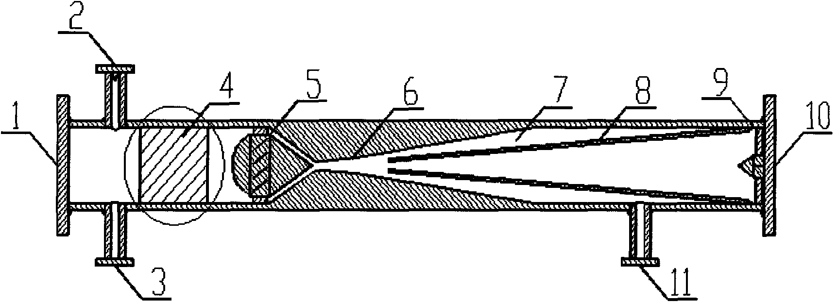
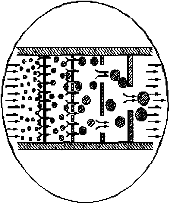
[0037] The implementation of the pre-nucleation supersonic vortex tube is illustrated by taking the dehydration of high-pressure natural gas as an example. The process flow is as follows Figure 5 shown. Composed of raw gas storage tank 16, raw gas separator 17, raw gas filter separator 18, gas-gas heat exchanger 19, fine filter 20, pre-nucleation supersonic vortex tube 21, gas-water separator 22, dehydrated dry gas Tank 23, water storage tank 24 and drainage tank 25 constitute;

[0038] The raw material gas storage tank 16 is connected with the raw material gas filter separator 18 through the raw material gas separator 17; the raw material gas filter separator is connected with the gas-gas heat exchanger 19; the gas-gas heat exchanger 19 is connected with the fine filter 20; the fine filter 20 is connected to the feed gas inlet 1 of the pre-nucleation supersonic vortex tube 21; the condensate outlet 11 of the pre-nucleation supersonic vortex tube 21 is connected to the gas-w...


PUM


Abstract

The invention relates to a natural gas dehydration method using a pre-nucleating supersonic vortex tube, which comprises the following steps of: introducing a raw material gas into a raw material gas separator and a raw material gas filter separator to remove large particles, cooling the raw material gas, removing fine solid particles through a fine filter, and introducing the raw material gas into the pre-nucleating supersonic vortex tube; adding a nucleating agent from a nucleating agent inlet or discharging the nucleating agent from a nucleating agent outlet, forming proper particle size through a coalescent nucleating device, generating vortex rotation in a vortex generator, and accelerating and cooling the raw material gas through a Laval nozzle; introducing the raw material gas intoa liquid separating cavity under the action of centrifugal force, and introducing the raw material gas into a gas-liquid separator through a condensate outlet; eliminating the vortex of a gas flow inthe center of the tube through a rectifier, introducing a gas mixture separated from a dry gas outlet and the gas-liquid separator into a gas-gas heat exchanger, exchanging heat with the raw materialgas to heat the raw material gas, exporting the gas mixture, introducing water separated from the raw material gas separator, the raw material gas filter separator and the gas-liquid separator into awater storage tank, and discharging the water. After water-containing natural gas is treated by the natural gas dehydration process using the pre-nucleating supersonic vortex tube, the dew point of water reaches subzero 5 DEG C, and the exporting requirement is satisfied.

Description

Technical field: [0001] The invention relates to a gas-liquid separation pre-nucleation supersonic vortex tube natural gas dehydration method which uses pressure difference to generate temperature drop and is used for removing high boiling point components in gas. Background technique: [0002] Scientists have discovered that using supersonic vortex tube technology and wellhead pressure can form low temperature, which can separate high boiling point components such as water and heavy hydrocarbons in natural gas. [0003] For the supersonic vortex tube dehydration technology, the patents formed by Translang and Twister companies: [0004] 1. "Supersonic separator apparatus and method" (US6776825B2) [0005] 2. "Method of and apparatus for the separation of components of gasmixtures and liquefaction of a gas" (US6372019B1) [0006] 3. "Nozzle for supersonic gas flow and an inertia separator" (US6513345B1) [0007] Domestically formed (applied) supersonic vortex tube patents...

Claims


Application Information

Patent Timeline
Patent Type & Authority Applications(China)
IPC IPC(8): B01D53/26C10L3/10B01D45/16
Inventor 计维安高晓根黄黎明常宏岗宋彬温冬云熊钢
Owner PETROCHINA CO LTD
Why Eureka
Try Eureka