Continuous casting method and device for aluminum alloy compounded ingot

A technology of composite ingot and aluminum alloy, which is applied in the field of aluminum alloy casting to achieve the effects of improving the yield, easy realization and control, and no pores, looseness and impurities.

Active Publication Date: 2011-09-14
NORTHEASTERN UNIV
View PDF6 Cites 10 Cited by
  • Summary
  • Abstract
  • Description
  • Claims
  • Application Information

AI Technical Summary

Problems solved by technology

[0009] Aiming at the technical problems in the preparation of existing aluminum alloy ingots, the p

Method used


Image

  • Continuous casting method and device for aluminum alloy compounded ingot
  • Continuous casting method and device for aluminum alloy compounded ingot
  • Continuous casting method and device for aluminum alloy compounded ingot

Examples


Embodiment 1

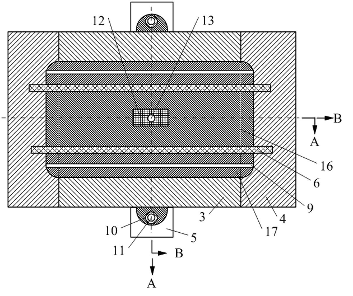
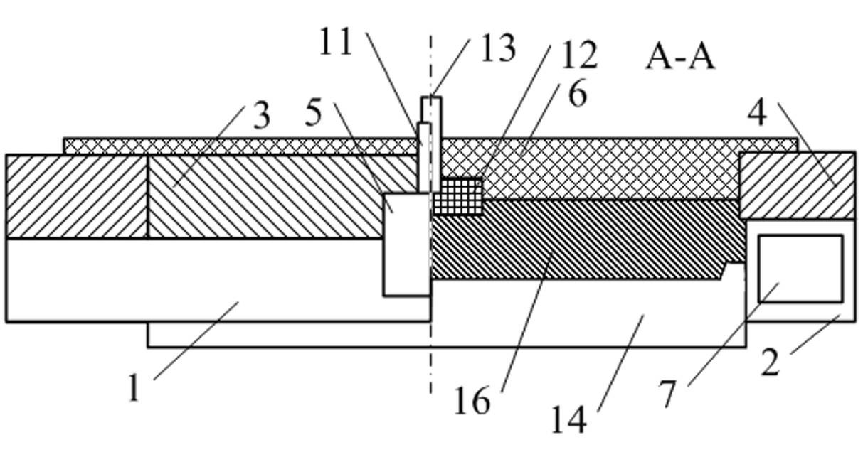
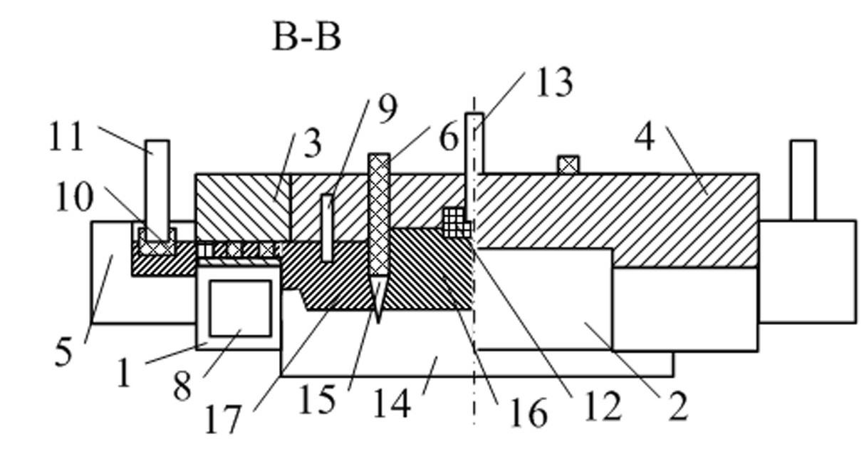
[0057] The continuous casting device structure of aluminum alloy composite ingot is as follows: figure 1 As shown, the A-A section structure is as follows figure 2 As shown, the cross-sectional structure of B-B plane is as follows image 3 As shown, it includes split crystallizer, alloy liquid distributor 3, hot top plate 4 and dummy ingot 14;

[0058] Split crystallizer structure such as Figure 4 with Figure 5 As shown, it is composed of two large surface water tanks 1 and two side water tanks 2;

[0059] In the continuous casting device for aluminum alloy composite ingots, an alloy liquid distributor 3 is connected above each large surface water tank 1, a hot top plate 4 is connected above each side water tank 2, and dummy ingots 14 are located at the bottom of the split crystallizer, each The lower surface of the hot top plate 4 is connected to a side water tank 2 and two large surface water tanks 1 at the same time; the two ends of each alloy liquid distributor 3 ar...

Embodiment 2

[0083] The structure of the continuous casting device for aluminum alloy composite ingot is the same as that in Example 1, the differences are: (1) the top of the large surface water tank is higher than the top of the side water tank, and the height difference between the two is 30 mm; (2) the material of the hot top plate is Calcium silicate board, the height is 180mm, and the height of the alloy liquid distributor is 150mm; (3) The bottom of the front plate of the cooling plate is 20mm lower than the upper edge of the large water tank; the heat insulation layer of the front plate is located in the melt chamber of the surface material of the cooling plate One side; (4) The inner wall of the split crystallizer is made of copper; (5) One end of the alloy liquid distributor extends to the inside of the split crystallizer, and the distance between the extended end and the inner wall of the split crystallizer is 5mm; one end of the hot top plate Extend to the inside of the split cr...


PUM

PropertyMeasurementUnit
Heightaaaaaaaaaa
Shear strengthaaaaaaaaaa

Abstract

The invention discloses a continuous casting method and a continuous casting method for an aluminum alloy compounded ingot and belongs to the technical field of aluminum alloy casting. The device comprises a split crystallizer, an alloy liquid distributor, a hot top plate and a dummy ingot; the upper part of the dummy ingot is fixedly connected with two baffle plates; the upper part of each baffle plate is connected with a cooling plate; and two cooling plates divide the interior of the split crystallizer into a core material melt cavity and a coating material melt cavity. The method comprises the following steps of: smelting, refining and standing two kinds of alloys to be compounded; introducing cooling water into a cooling plate water cavity and a water box and keeping the water flowing; leading the core material alloy liquid into the core material melt cavity; leading the coating material alloy liquid into the coating material melt cavity; and starting the aluminum alloy and casting. The device and the method can ensure that the coating material alloy liquid flow uniformly and has a stable liquid surface and uniform temperature, and can eliminate the triangular area with high cooling intensity, ensure that a supporting surface formed under the cooling plate has the uniform temperature along the horizontal direction of the cooling plate and ensure the comprehensive metallurgical combination of the compounded surface.

Description

technical field [0001] The invention belongs to the technical field of aluminum alloy casting, and in particular relates to a continuous casting method and a device for aluminum alloy composite ingot casting. Background technique [0002] Due to the single performance of conventional aluminum alloys, they cannot well meet the comprehensive requirements of multiple performances in engineering such as vehicles, structures, and electronics. Therefore, composite materials have become the focus of new material research and development. Due to its low cost and high comprehensive performance, layered composite materials are the most widely used composite materials with the largest production volume. Among them, composite aluminum materials have high strength, and at the same time have comprehensive properties such as corrosion resistance (decoration), weldability, and easy forming. It is the fastest growing composite material, and composite sheet and strip is currently the most use...

Claims


Application Information

Patent Timeline
IPC IPC(8): B22D11/14
Inventor 崔建忠蒋会学秦克赵志浩王向杰朱庆丰
Owner NORTHEASTERN UNIV
Why Eureka
Try Eureka