Solar sludge drying triple-effect device
A sludge drying and solar energy technology, applied in solar thermal devices, solar thermal power generation, heating devices, etc., can solve the problems of high cost, high energy consumption, high operating costs, reduce unnecessary waste, strengthen further processing, The effect of improving drying efficiency
- Summary
- Abstract
- Description
- Claims
- Application Information
AI Technical Summary
Problems solved by technology
Method used
Image

Examples
Embodiment Construction
[0013] The present invention will be further described below in conjunction with specific embodiment:
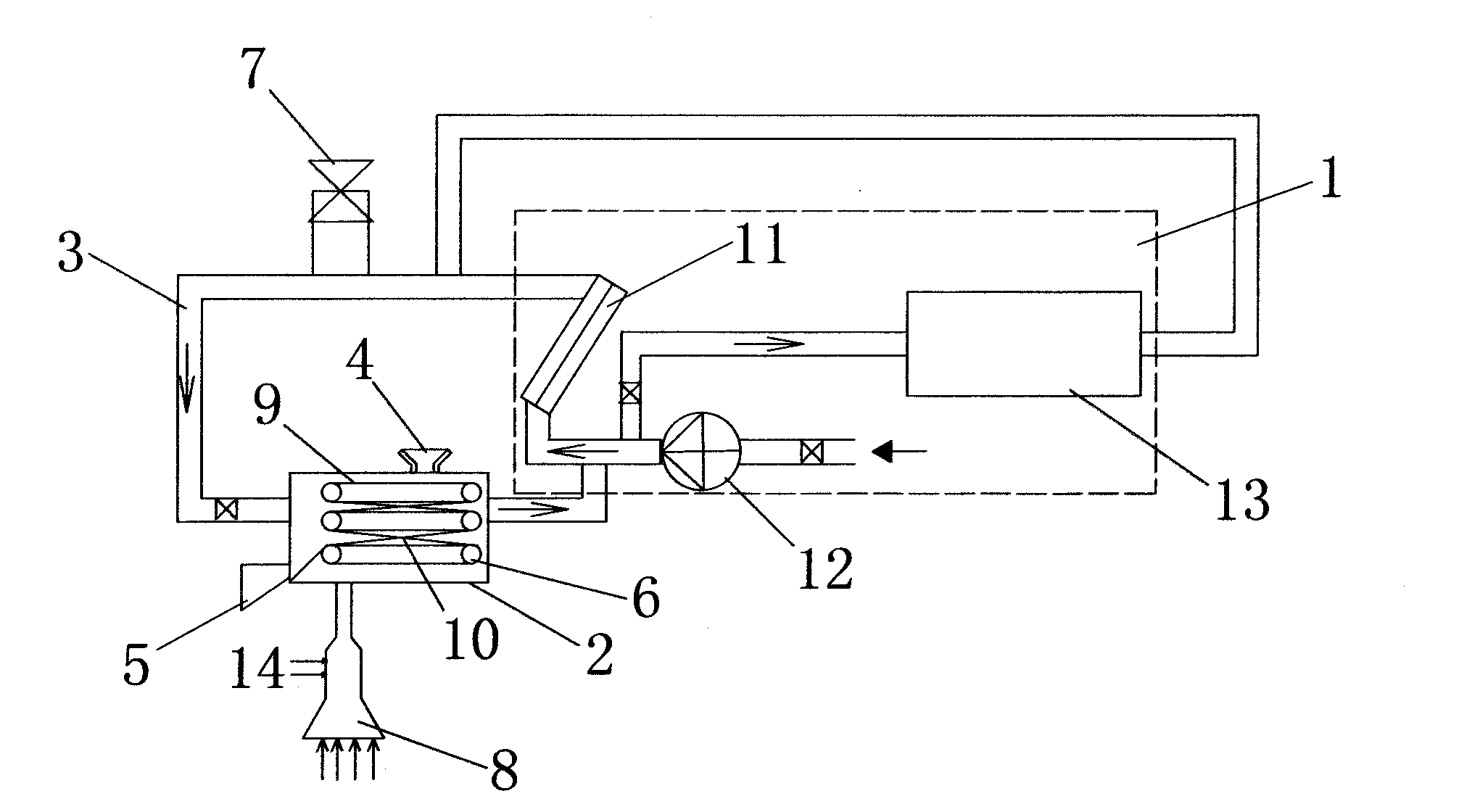
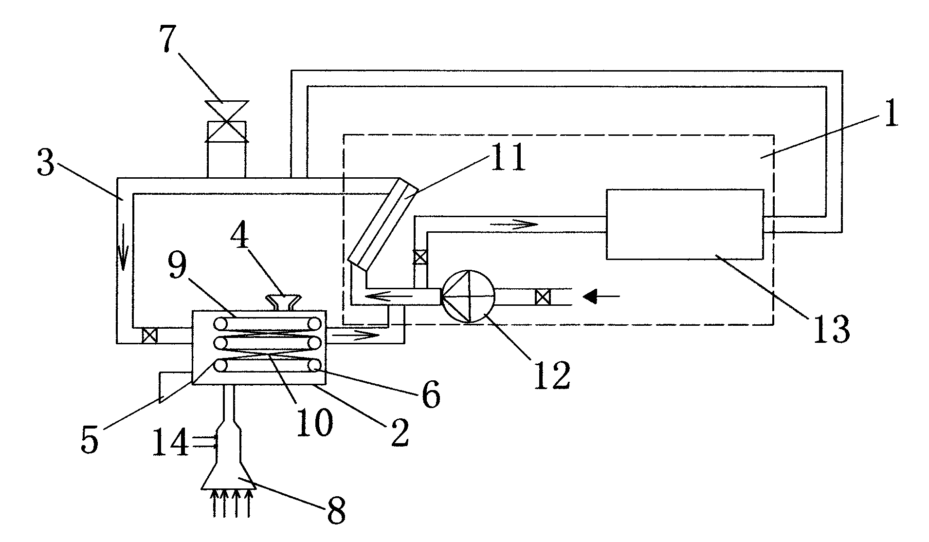
[0014] Such as figure 1 As shown, a solar sludge drying triple effect device includes a heat collector 1 and a drying chamber 2 in sequence according to the air intake direction, and the drying chamber 2 is connected to the heat collector 1 through a ventilation pipe 3, and the drying chamber 2 above A feed hopper 4 is provided, a discharge port 5 is provided under the side of the drying chamber, a sludge conveyor 6 is provided in the drying chamber 2, a vent valve 7 is provided on the ventilation pipe 3, and a discharge valve 7 is provided below the drying chamber 2. Gas furnace 8, the sludge conveyor 6 includes a bottom-to-bottom three-layer conveyor belt 9 and vertically staggered guide rails 10 installed between adjacent two-layer conveyor belts 9, and the heat collector 1 includes a plate heat collector 11. The fan 12 connected to the plate heat collector 11, the heat ...
PUM
 Abstract
Description
Claims
Application Information
 - R&D
- Intellectual Property
- Life Sciences
- Materials
- Tech Scout
- Unparalleled Data Quality
- Higher Quality Content
- 60% Fewer Hallucinations
Browse by: Latest US Patents, China's latest patents, Technical Efficacy Thesaurus, Application Domain, Technology Topic, Popular Technical Reports.
© 2025 PatSnap. All rights reserved.Legal|Privacy policy|Modern Slavery Act Transparency Statement|Sitemap|About US| Contact US: help@patsnap.com