Brake actuating mechanism for distributed electronic hydraulic brake system of automobile

A technology of actuators and hydraulic brakes, which is applied in the direction of brake actuators, brake components, brake types, etc., can solve the problems of pressure estimation accuracy and control quality degradation, large vibration and shock of motor materials, long axial dimension of the system, etc. , to achieve the effect of shortening the braking distance of the car, short response time and improving economy

Active Publication Date: 2011-09-14
TSINGHUA UNIV
View PDF7 Cites 14 Cited by
  • Summary
  • Abstract
  • Description
  • Claims
  • Application Information

AI Technical Summary

Problems solved by technology

EMB is a distributed brake-by-wire system that uses motors as power sources. The current disadvantages of the EMB system are: because the motor is close to the wheel, its working environment is very harsh, and the temperature of the motor can change up to 200°C during the work process. Using a permanent magnet motor will result in a 20% to 25% change in the motor torque constant, and the motor material must also be able to withstand large vibration shocks
But this technical route also has some disadvantages: 1. In order to obtain higher pressure estimation accuracy and pressure control quality, more pressure sensors and linear proportional valves need to be used in an EHB system, such as Toyota's first-generation EHB The system (named ECB) uses 6 pressure sensors and 6 linear proportional valves, which will significantly increase the cost of the system
2. If the number of pressure sensor

Method used


Image

  • Brake actuating mechanism for distributed electronic hydraulic brake system of automobile
  • Brake actuating mechanism for distributed electronic hydraulic brake system of automobile
  • Brake actuating mechanism for distributed electronic hydraulic brake system of automobile

Examples


Embodiment 1

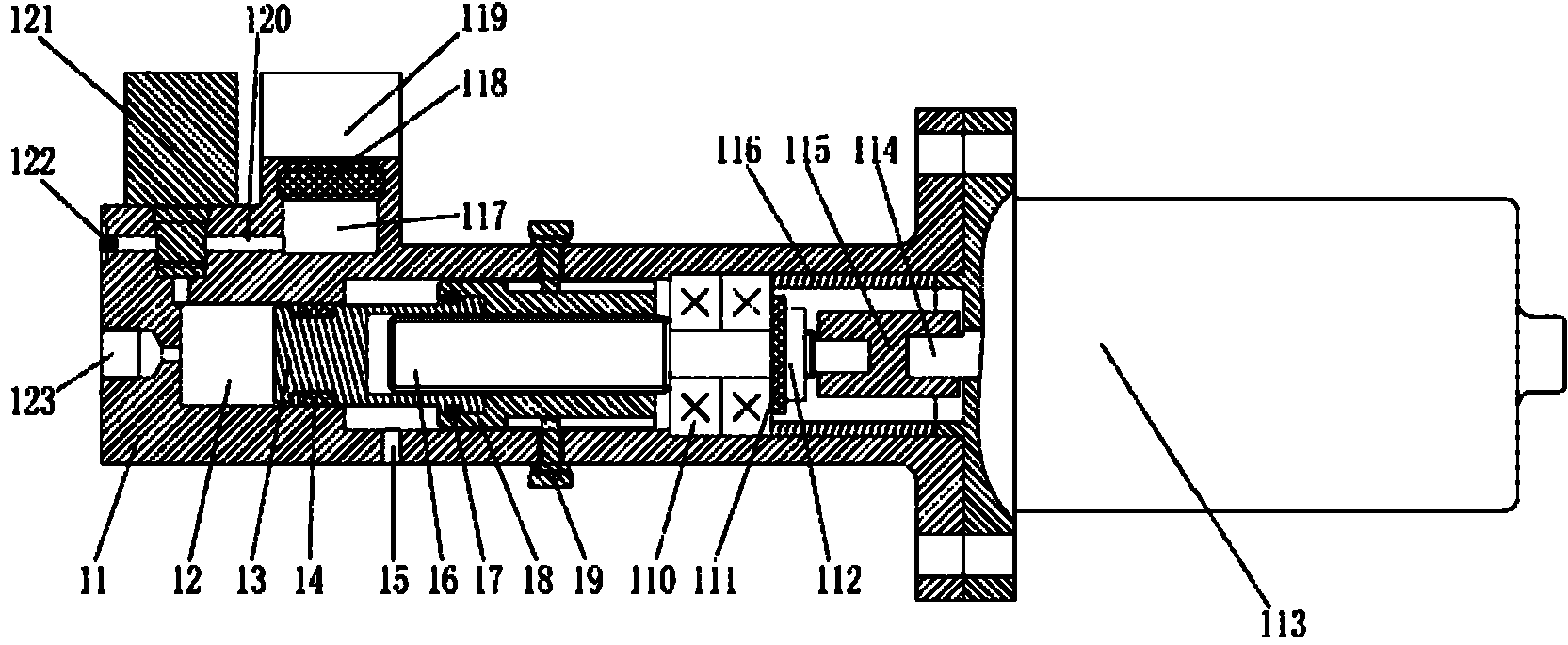
[0025] The overall structure of this embodiment, such as figure 1 As shown, it includes a housing 11, a piston 13 with a sealing ring 14, a piston driving device, a DC motor 113, a solenoid valve 121, an oil pot 119 with a sealing ring 118; the housing 11 includes a central hole The right end face, the stepped hole formed in the housing 11 consisting of left, middle and right circular holes and the oil storage chamber 117 horizontally separated from the stepped hole; the piston 13 with the sealing ring 14 is placed in the left circular hole, The piston driving device is placed in the middle and right circular holes; the left end of the piston 13 with the sealing ring 14 and the left circular hole form the brake oil chamber 12, and the right end of the piston 13 with the sealing ring 14 and the piston driving device The piston driving device is connected to the DC motor 113 installed on the right end surface of the housing 11, the solenoid valve 121 and the oil pot 119 with the...

Embodiment 2

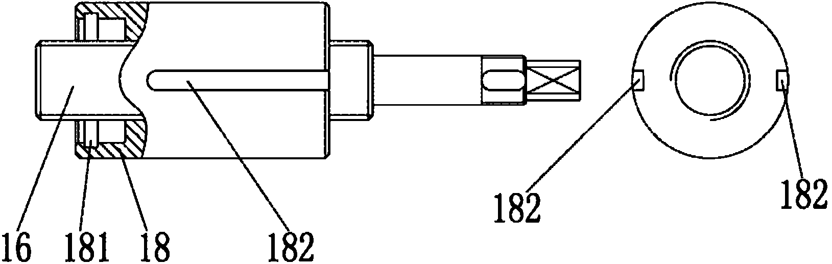
[0034] The structure of this embodiment, such as Figure 4 , Figure 5As shown, the difference between this embodiment and the specific implementation of embodiment 1 is that the designed constraint structure to prevent the rotation of the nut is different, so the designed housing 21 and nut 28 are also slightly different from the housing 11 and nut 18 in embodiment 1. There are different. Specifically, this embodiment cancels the anti-rotation constraining structure of the anti-rotation screw 19 and nut anti-rotation groove 182 in Embodiment 1, but processes two symmetrical planes on the outer surface of the nut 28. On the inner wall of the housing 21 where the two symmetrical planes are located, two corresponding planes are also processed (for example, milled out or cast out), and the planes on the inner wall of the housing 21 match the planes of the nut 28 to form the housing 21 inner wall and the contact plane 29 of the nut 28, thereby preventing the rotation of the nut ...

Embodiment 3

[0036] The structure of this embodiment, such as Figure 6 As shown, the difference between this embodiment and Embodiment 1 is that the snap ring, the piston snap ring groove and the nut snap ring groove are cancelled, and the piston 33 and the nut 38 are no longer fixedly connected by the snap ring in Embodiment 1, but The fixed connection between the piston 33 and the nut 38 is realized through the interference fit between them. The interference fit between the piston 33 and the nut 38 is realized by a cold packing process: the piston 33 is dropped into a coolant (such as liquid nitrogen) for a certain period of time so that the radial dimension of the piston 33 shrinks, and then the piston 33 can be Insert in the nut 38, wait for the piston 33 to return to the original radial dimension along with the recovery of temperature, the piston 33 has just realized the interference fit with the nut 38, and the two have just been connected firmly. Of course, other suitable methods ...


PUM


Abstract

The invention relates to a brake actuating mechanism for a distributed electronic hydraulic brake system of an automobile, and belongs to the technical field of automobile manufacturing. The mechanism comprises a shell, a piston, a driving device, a direct current motor, a solenoid valve and an oil can; the shell comprises a right end surface, a step hole consisting of a left round hole, a middleround hole and a right round hole and an oil storage cavity separated by the step hole; the piston and the driving device are arranged in the step hole; a brake oil cavity is formed by the piston andthe left round hole; the piston is connected with the driving device; the driving device is connected with the direct current motor; the solenoid valve and the oil can are respectively arranged at the outer sides of the shell; the oil storage cavity is communicated with the oil can; the lower part of the oil storage cavity and the upper surface which is close to the left end of the brake oil cavity are respectively provided with a horizontal through hole and a vertical through hole which are communicated with the solenoid vale; and oil outlet holes and safety holes are respectively arranged on the left surface of the brake oil cavity and below the wall of the intermediate round hole. The brake actuating mechanism provided by the invention has a simple and compact structure, can rapidly establish brake hydraulic pressure, and is beneficial for shortening the brake distance and increasing the running safety.

Description

technical field [0001] The invention relates to a braking actuator used in a distributed electronic hydraulic braking system of an automobile, belonging to the technical field of automobile manufacturing. Background technique [0002] The structure of a traditional automotive hydraulic braking system, including a brake pedal, a vacuum booster, a master cylinder, a hydraulic control unit and an electronic control unit, brakes for each wheel, brake lines connecting the master cylinder and the hydraulic control unit, and connecting hydraulic pressure Control unit and brake lines for the individual wheel brakes. There is usually a time delay of 0.3s to 1.0s from the time when the driver produces a braking intention to when the driver's foot steps on the brake pedal. This period is called the driver's reaction time. After the driver steps on the brake pedal, as the brake pedal moves forward, the vacuum booster assists the driver's physical strength and pushes the piston of the m...

Claims


Application Information

Patent Timeline
IPC IPC(8): F16D65/36F16D65/28
Inventor 宋健王治中王语风于良耀李亮王伟玮陈友飞马良旭孟爱红吴凯辉
Owner TSINGHUA UNIV
Why Eureka
Try Eureka